For GX460 (2010–2019) owners with basic wiring experience. The 2020-2023 GX460 has this feature from the factory, and the GX470 (2003–2009) takes a different route covered at the end of this guide.
Quick answer
The feature gap. Lexus gave the GX460 a lane change flasher for the 2020 model year. The 2010-2019 trucks flash the turn signals only while you hold the lever partway, and the GX460 factory manual lists no setting that adds the tap function to those years.
The fix. The conversion in this guide moves the eight working wires from the factory flasher connector to a standard Toyota 8-pin flasher socket, then plugs in an 8-pin lane change relay. The replacement relay watches for a short tap on the lever and finishes the flash count on its own.
The tradeoff. Trucks with the factory tow package carry a separate powered feed for the trailer light circuit inside the flasher. The 8-pin relay has no terminal for that feed, so this conversion suits owners who do not tow with the truck.
The effort. The job takes about an hour. It needs trim removal under the driver side dash, eight wire splices, and a full light test before the panels go back on.
Why the early GX460 missed the feature
The GX460 turn signals run through a replaceable flasher assembly mounted under the driver side of the instrument panel. The flasher receives the lever inputs and the hazard switch input, and it drives the left and right signal outputs. Lexus kept the same flasher assembly, part 81980-60160, in production across the 2020 model year, and the tap function arrived that year as logic inside the combination meter. The earlier trucks pair the same flasher with a meter that never sends a tap command, so a flasher swap from a 2020 truck changes nothing on a 2010-2019 truck. The customize tables in the GX460 factory manual confirm the gap, since the lane change flash count parameter appears only in the 2020 and later sections.
The GX470 took the simpler path. Its flasher is also a separate assembly, and owners fit the same family of 8-pin lane change relays through a plug-in harness. The GX460 side splits by tow package, with an 18-cavity housing on tow package trucks and an 8-cavity housing on the rest, and the splice in this guide maps the eight working wires by function onto the new socket either way.
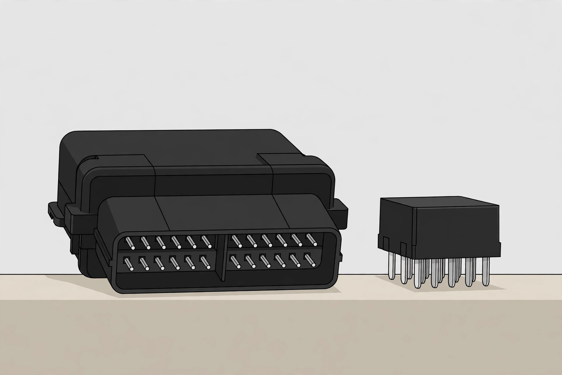
Parts and tools
| Item | Detail |
|---|---|
| Lane change flasher relay | Standard Toyota 8-pin (CF18) relay with a tap function. The Diode Dynamics SmartTap CF18, part DD4015, has a programmable tap count. The Valenti Euro Winker ER-01 costs less and flashes a fixed three times per tap. |
| Flasher socket | Toyota flasher connector housing 90980-10799 with eight pre-crimped terminal leads (F090-SMTS on 0.5 sq wire), pushed into the housing to form the socket. |
| Wire supplies | Butt connectors or solder, heat shrink tubing, electrical tape, and a wire cap for the trailer feed |
| Tools | Trim panel tool, 10 mm socket and ratchet, wire stripper, crimper, multimeter, flashlight |
Before you start
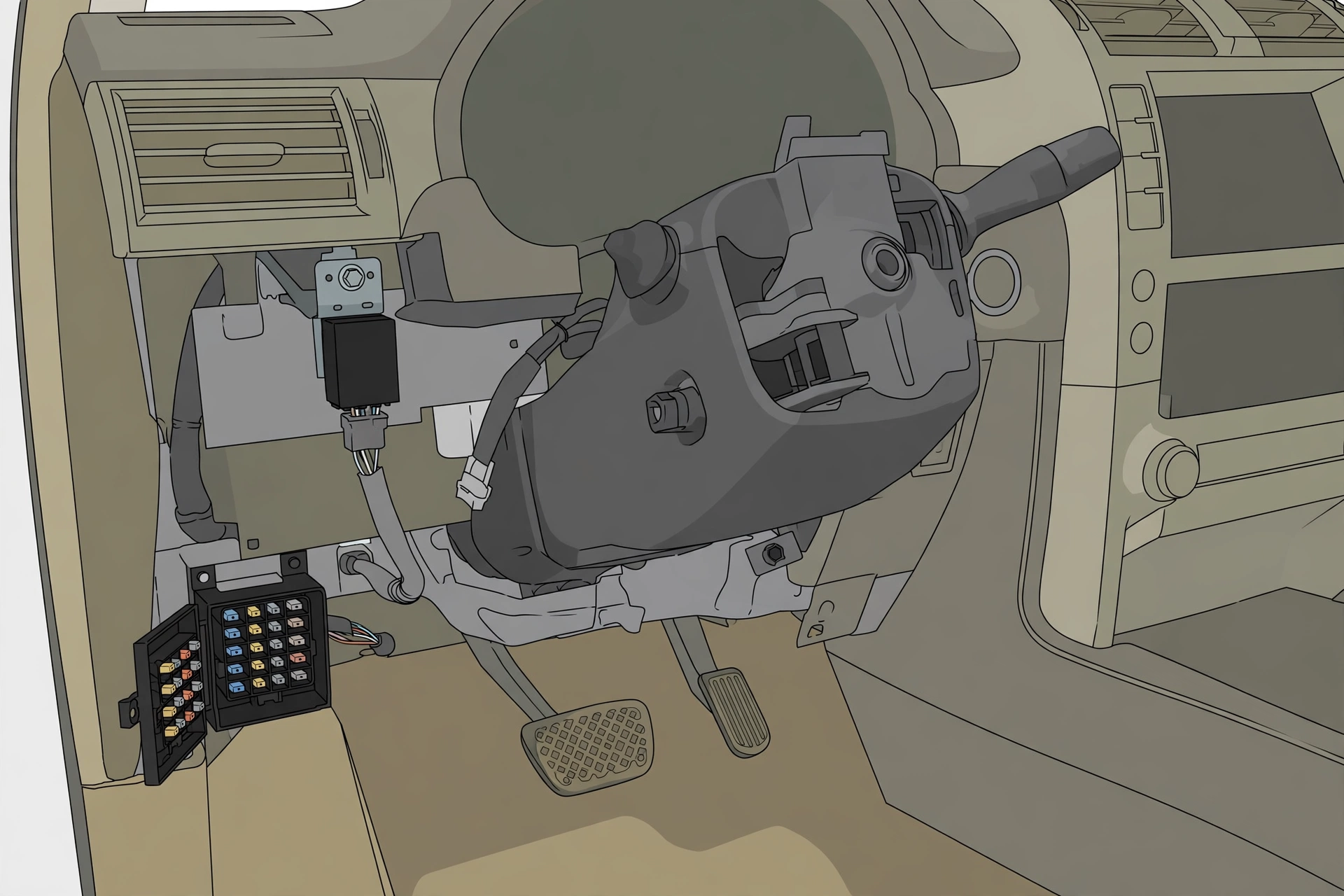
Confirm your flasher. Turn the hazards on and listen under the driver side dash. The clicking comes from the flasher assembly, and it hangs on a bracket high at the left end of the dash, below the driver side vent and above the left end of the lower instrument panel. One nut holds it to its bracket. The unit already in the truck is 81980-60160 on trucks with the factory tow hitch, and 81980-60130 on 2010-2012 trucks built without the tow hitch.
Read the tow warning again. This conversion leaves the trailer light feed disconnected. Owners who tow should stop here and keep the factory flasher.
Plan the return path. The splice method in this guide taps the factory wires and leaves the factory connector in place with the flasher unplugged. Returning to stock means removing the taps, reinsulating each wire, and plugging the factory flasher back in.
2010 to 2019 GX460: rewiring the flasher connector for an 8-pin lane change relay
- Disconnect the negative battery terminal and wait a few minutes before working under the dash.
- Remove the driver door scuff plate and the cowl side trim board at the left kick panel.
- Remove the No. 1 instrument panel under cover, the instrument panel finish panel end on the left, and the lower instrument panel finish panel. The GX460 factory manual lists this order for flasher access.
- Unplug the flasher connector and remove the single nut that holds the flasher assembly. Set the factory flasher aside. You can leave it out or bolt it back in place unplugged as a placeholder.
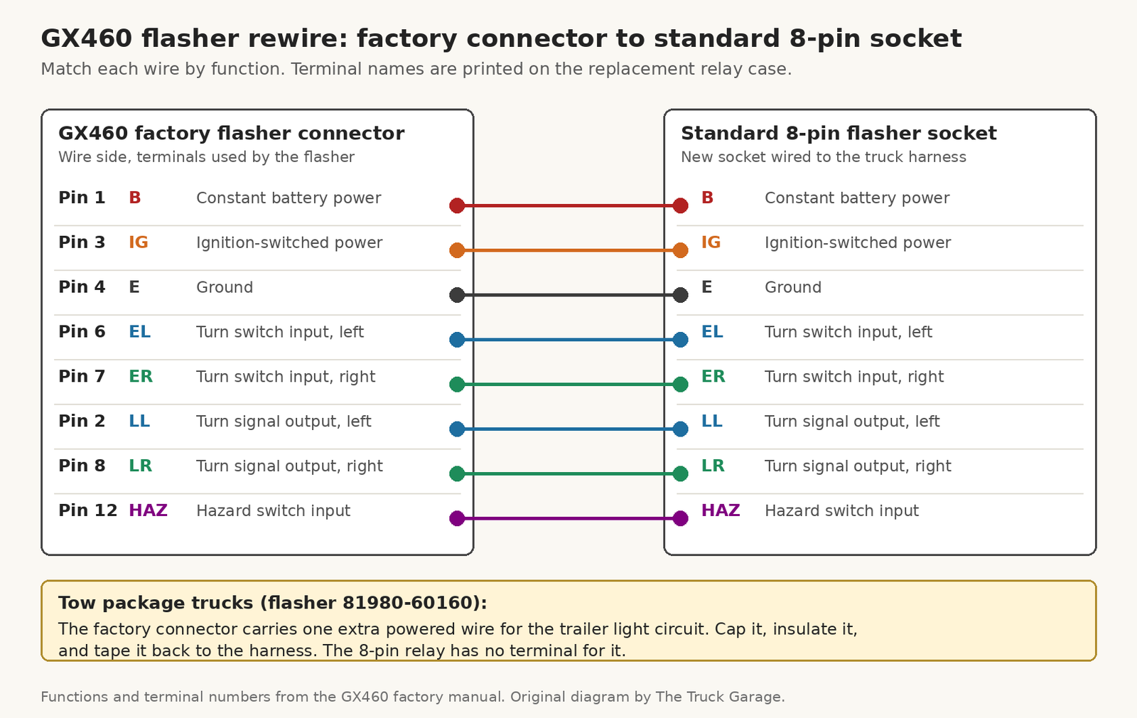
- Identify the eight working wires on the factory connector. The connector splits by tow package. Trucks with the factory tow hitch carry a white 18-cavity housing, and the flasher circuits use eight of its cavities. Trucks without the tow hitch carry a black 8-cavity housing, and all eight cavities work. The diagrams show both connector faces with the working cavities filled in their wire colors, and the table lists each wire by function name, cavity number for each housing, and vehicle-side wire color.
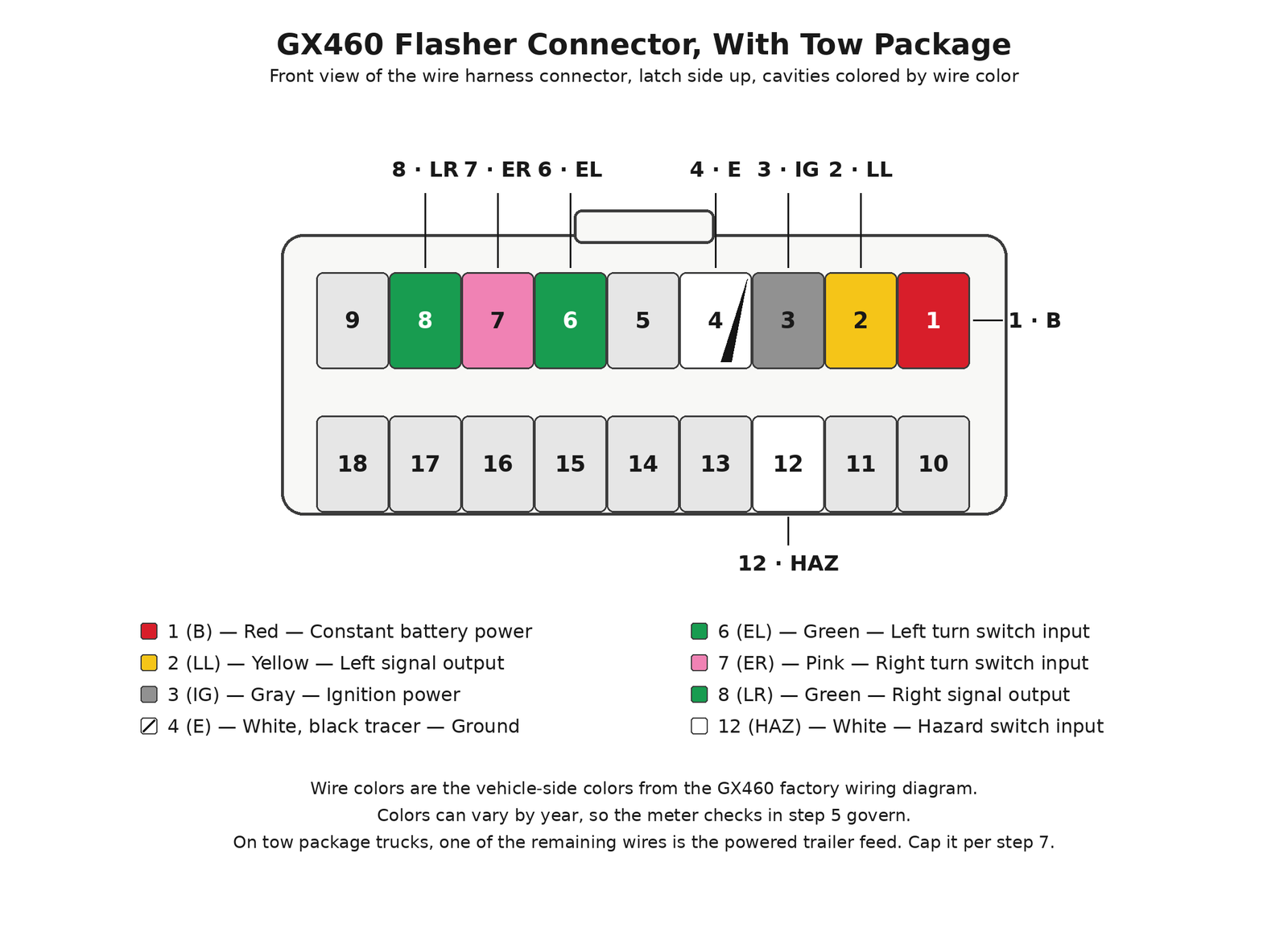
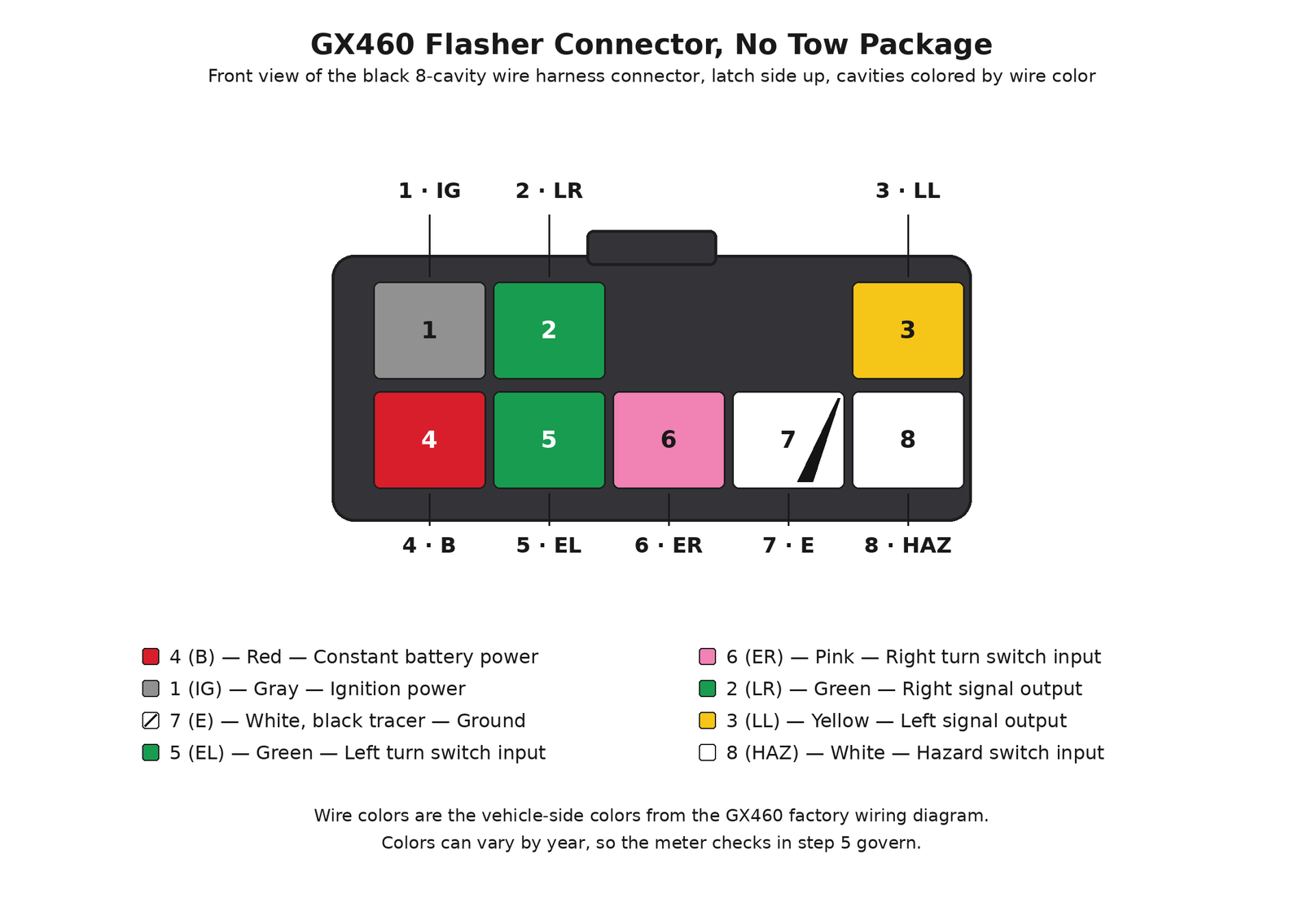
| Name | Function | Cavity, tow package | Cavity, no tow package | Wire color |
|---|---|---|---|---|
| B | Constant battery power | 1 | 4 | Red |
| IG | Ignition power | 3 | 1 | Gray |
| E | Ground | 4 | 7 | White with black tracer |
| EL | Left turn switch input | 6 | 5 | Green |
| ER | Right turn switch input | 7 | 6 | Pink |
| LL | Left signal output | 2 | 3 | Yellow |
| LR | Right signal output | 8 | 2 | Green |
| HAZ | Hazard switch input | 12 | 8 | White |
Verify each wire with a multimeter before you splice, since wire colors vary by year. Three checks confirm the power side on either housing. The B wire reads 11 to 14 V at all times, the IG wire reads 11 to 14 V with the ignition on, and the E wire reads below 1 Ω to body ground.
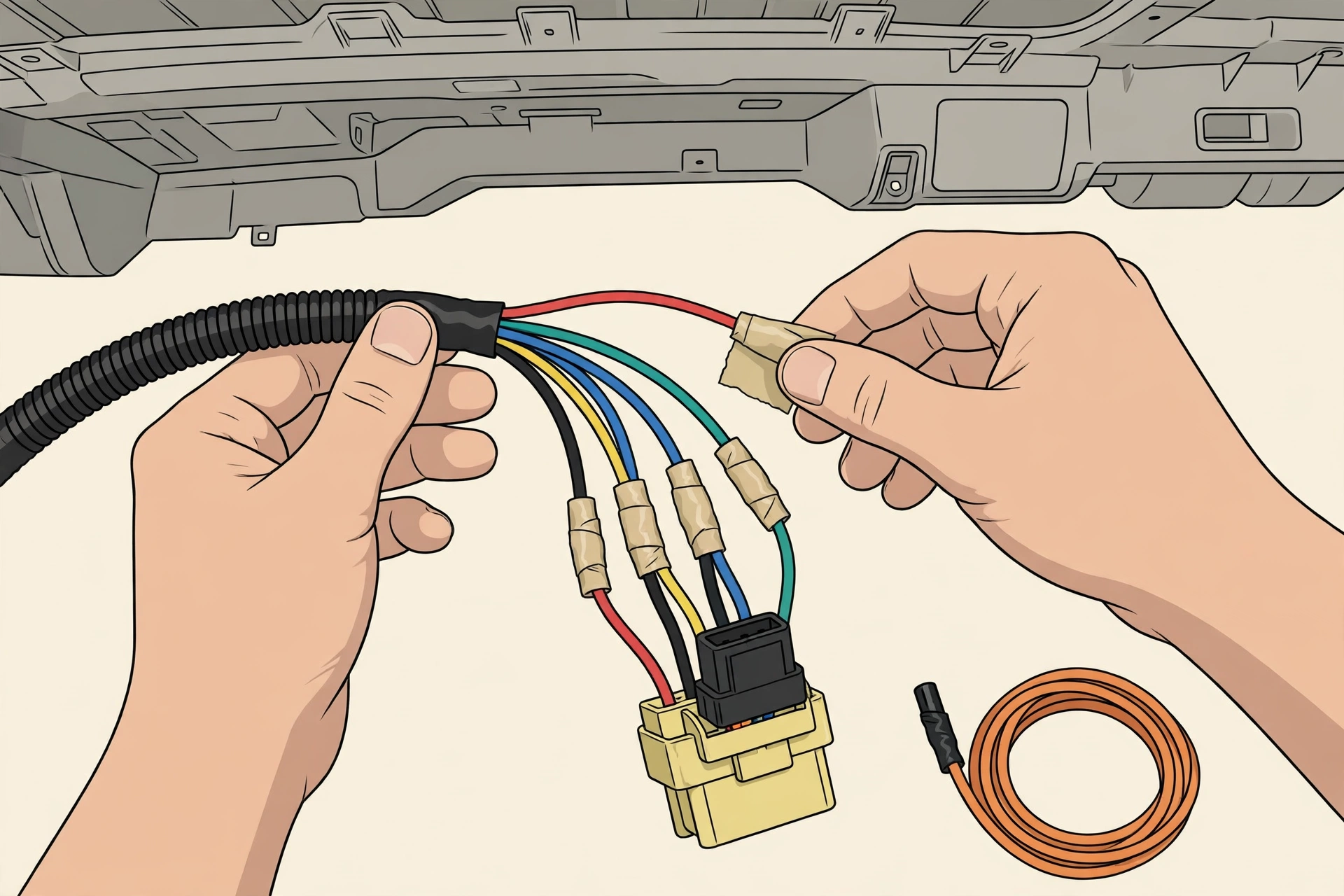
- Push the eight pre-crimped leads into the socket housing until each terminal locks. Splice each factory wire to the matching function lead on the new 8-pin socket. Match by function name, and follow the terminal names printed on the replacement relay case for the socket positions.
- On tow package trucks, find the one remaining powered wire in the factory connector. Cap it, insulate the cap with heat shrink or tape, and tape the wire back against the harness.
- Plug the lane change relay into the new socket and secure the socket so it cannot rattle against the dash structure.
Test everything before the panels go back
- Reconnect the battery.
- Tap the lever partway in each direction and release it. The signals should flash the relay’s tap count, then stop.
- Push the lever to the full turn position in each direction. The signals should flash until you cancel the lever or complete the turn.
- Run the hazard switch and confirm all four corners flash.
- Lock and unlock the truck with the remote and confirm the signal flash confirmation still works.
- Turn on the parking lights and headlights and repeat the tap test, since the relay shares the truck’s lighting circuits.
- Fix any missed function at the splice for that function name before you reinstall the trim. The diagram lists each output and input separately, so a dead left output points at the LL splice and a dead hazard points at the HAZ splice.
Programming the flash count
The SmartTap and similar 8-pin relays set the tap count through the lever. You hold the lever in a set pattern with the ignition on, and the relay stores the count. The relay ships with its own programming card, and the count options typically run from 3 to 8 flashes. Pick a count that covers a full lane change at highway speed. Most owners land on 4 or 5. Fixed-count relays such as the Valenti ER-01 skip this step and flash three times per tap.
GX470 owners
The 2003-2009 GX470 uses its own flasher assembly and takes the same style of 8-pin lane change relay through the GX470-specific harness route, with the non-DRL jumper wire 82241-35010 on trucks that need it. The GX460 rewire in this guide applies to the GX460 connector only.
Sources
- GX460 factory manual, lighting system sections covering the turn signal flasher assembly, its on-vehicle inspection terminal table, and its removal procedure.
- GX460 factory manual, 2020 and 2021 lighting customize sections covering the lane change flashing times parameter.
- 2020 GX460 owner’s manual, page 207, turn signal lever operating instructions.
- 2018 GX460 owner’s manual, turn signal lever operating instructions.
- Diode Dynamics SmartTap CF18 published specifications and fitment notes.
- Valenti Euro Winker ER-01 published specifications.
Leave a Reply