Reading time: ~22 minutes · Difficulty: advanced DIY (full weekend) · Engine: Toyota/Lexus 2UZ-FE 4.7L V8
This is the companion to the free overview guide. If you have not read that one, start there. It covers when to do the job, what to replace while you are in there, costs, and the torque spec table. This article assumes you have read it. It gives you the procedure itself, step by step, in the factory order, with the torque value at every fastener and shadetree alternatives where a home mechanic needs them. [manual]
Parts and tools
Get all of this before you start. The engine will sit open and undriveable between steps.
Parts:
- Aisin TKT-021 timing belt and water pump kit. Belt, water pump, hydraulic tensioner, idler pulleys, gaskets. [vendor] Aisin catalogs the TKT-021 for the full 2UZ-FE range, including every GX470 from 2003 to 2009. Do not buy the TKT-001 by mistake. It ships without the hydraulic tensioner. Buy from a reputable seller. Counterfeit Aisin kits exist. [community]
- Water pump gasket (included in the kit; have a spare if yours is not)
- Camshaft seals (x2) and crankshaft front seal. Optional but smart. They are behind the same covers and cost a few dollars each. [community]
- Timing cover gaskets [community]
- Accessory (serpentine) belt. The old one comes off during the job. [community]
- Toyota Super Long Life coolant. Capacity is 12.9 liters (13.6 US quarts). [manual]
- Thermostat, upper and lower radiator hoses, heater T-fittings. Optional while the system is drained. [community]
Tools:
- Torque wrench that reads in·lbf for the small fasteners and reaches 181 ft·lbf (245 N·m) for the crank bolt [manual]
- Crankshaft pulley holding tool (SST 09213-70011 or equivalent) and a damper puller set [manual]. Shadetree alternatives are in the steps below.
- Press or large bench vise for the tensioner [manual]
- 1.27 mm hex wrench. This pins the tensioner push rod in the compressed position. Note that 1.27 mm is exactly 0.05 inch, so a 0.05 in hex wrench is the same tool. [manual]
- Pliers for pulling the tensioner pin [manual]
- Standard socket set, jack and jack stands, drain pans
- A funnel. A spill-free funnel that seals to the radiator neck makes the refill cleaner. A plain funnel plus patience works too. [community]
Teardown
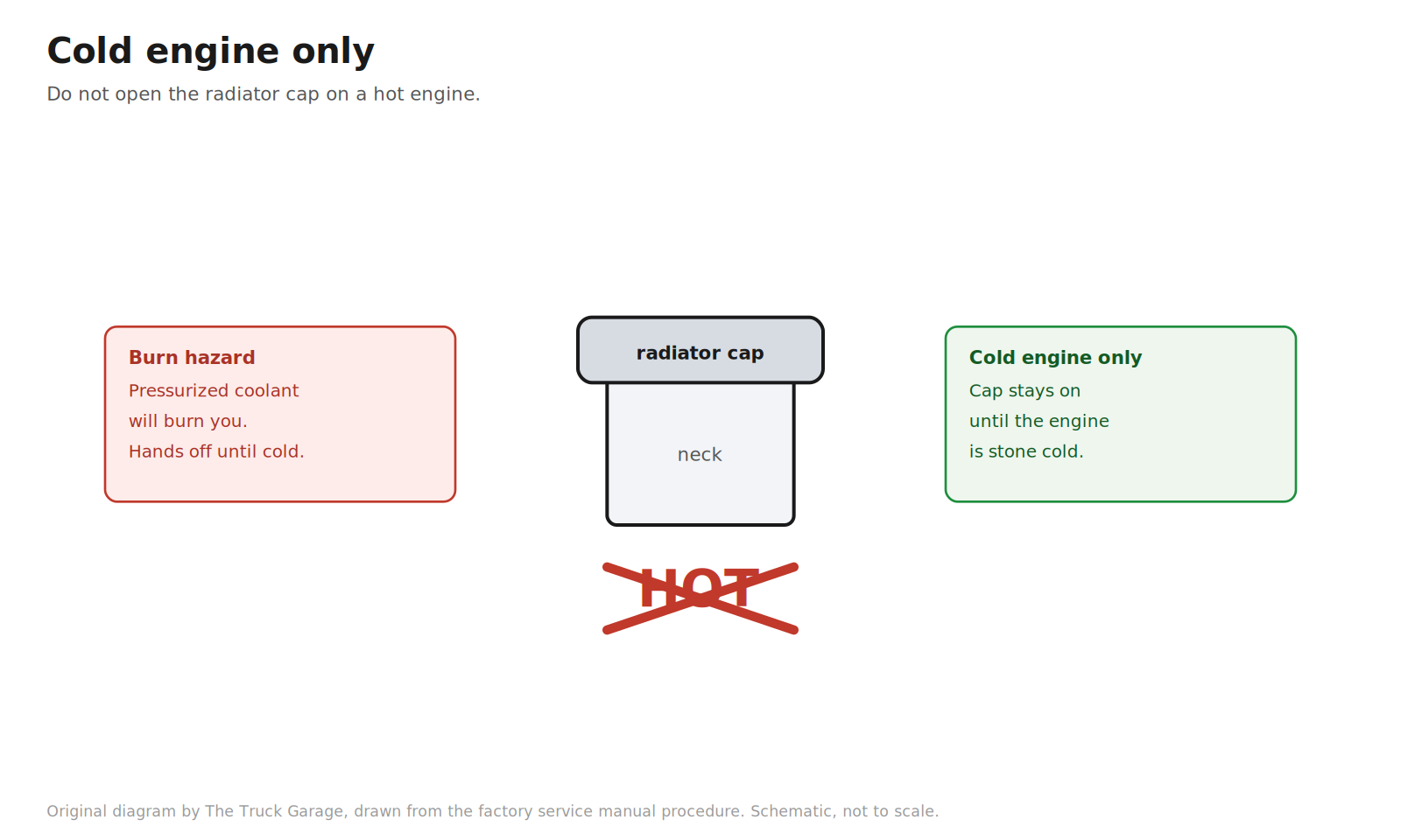
1. Work on a cold engine. Do not remove the radiator cap while the engine is hot. Pressurized coolant will burn you. [manual]
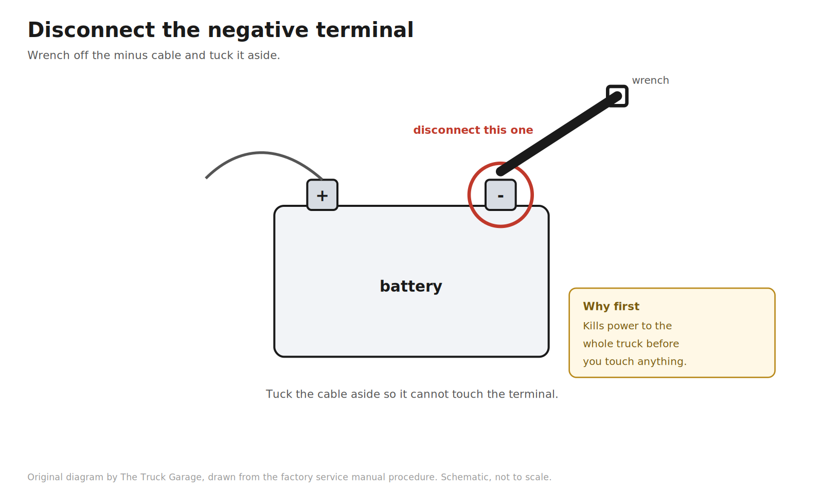
2. Disconnect the battery negative terminal. [manual]
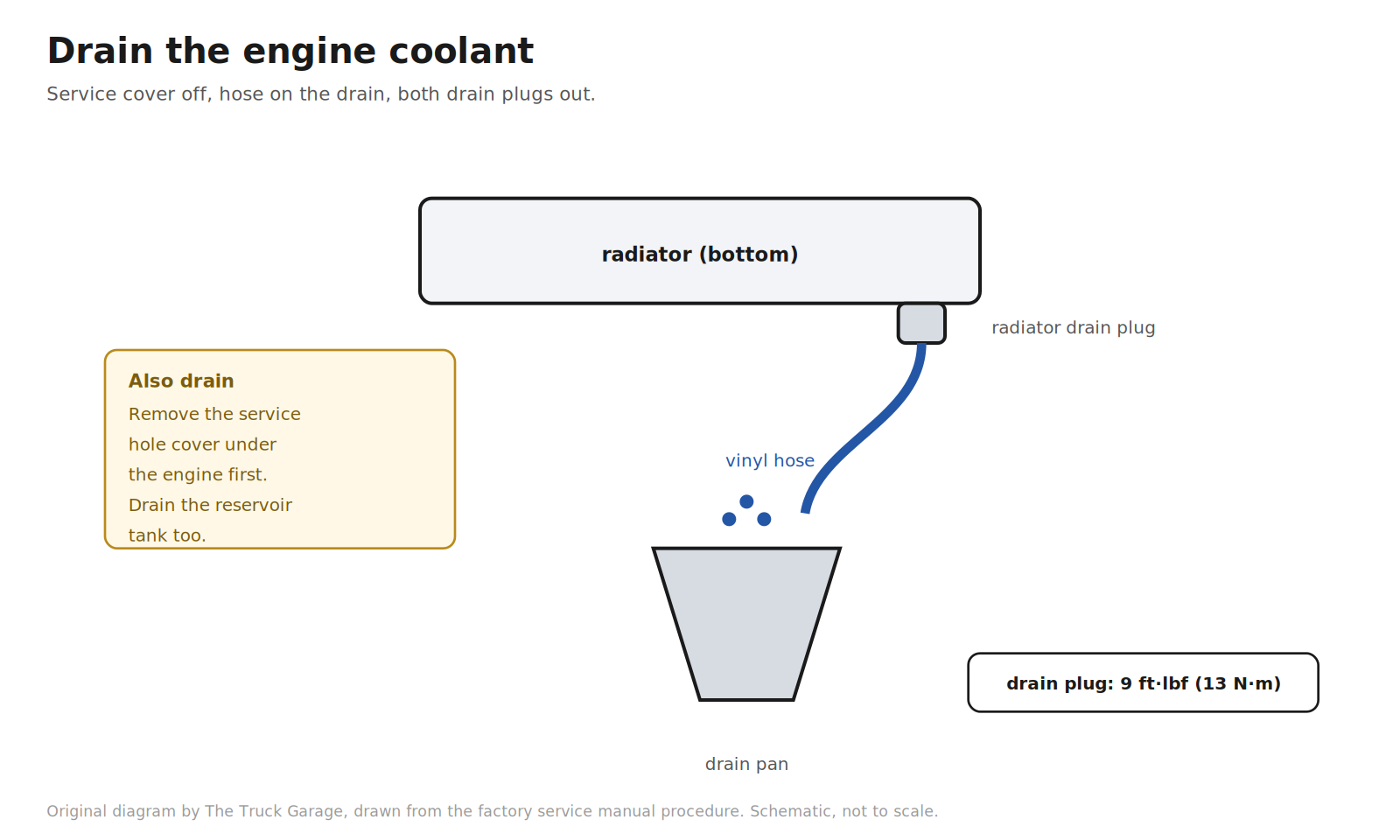
3. Drain the engine coolant. Remove the service hole cover under the engine. Fit a vinyl hose to the radiator drain. Loosen the radiator drain plug and the engine drain plug, and drain the coolant from the radiator. Drain the reservoir tank too. Close both drain plugs when done. The engine drain plug torques to 9 ft·lbf (13 N·m). [manual]
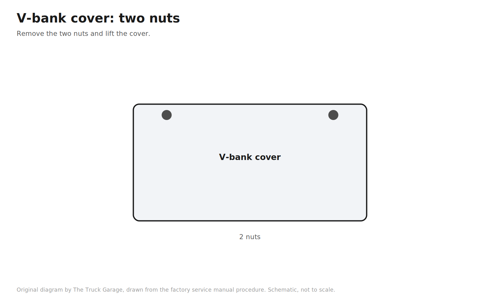
4. Remove the V-bank cover. Two nuts. [manual]
5. Remove the engine room side cover, the side cover LH, and the air cleaner hose. [manual]
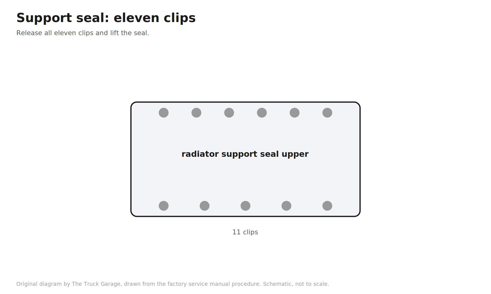
6. Remove the radiator support seal upper. Eleven clips. [manual]
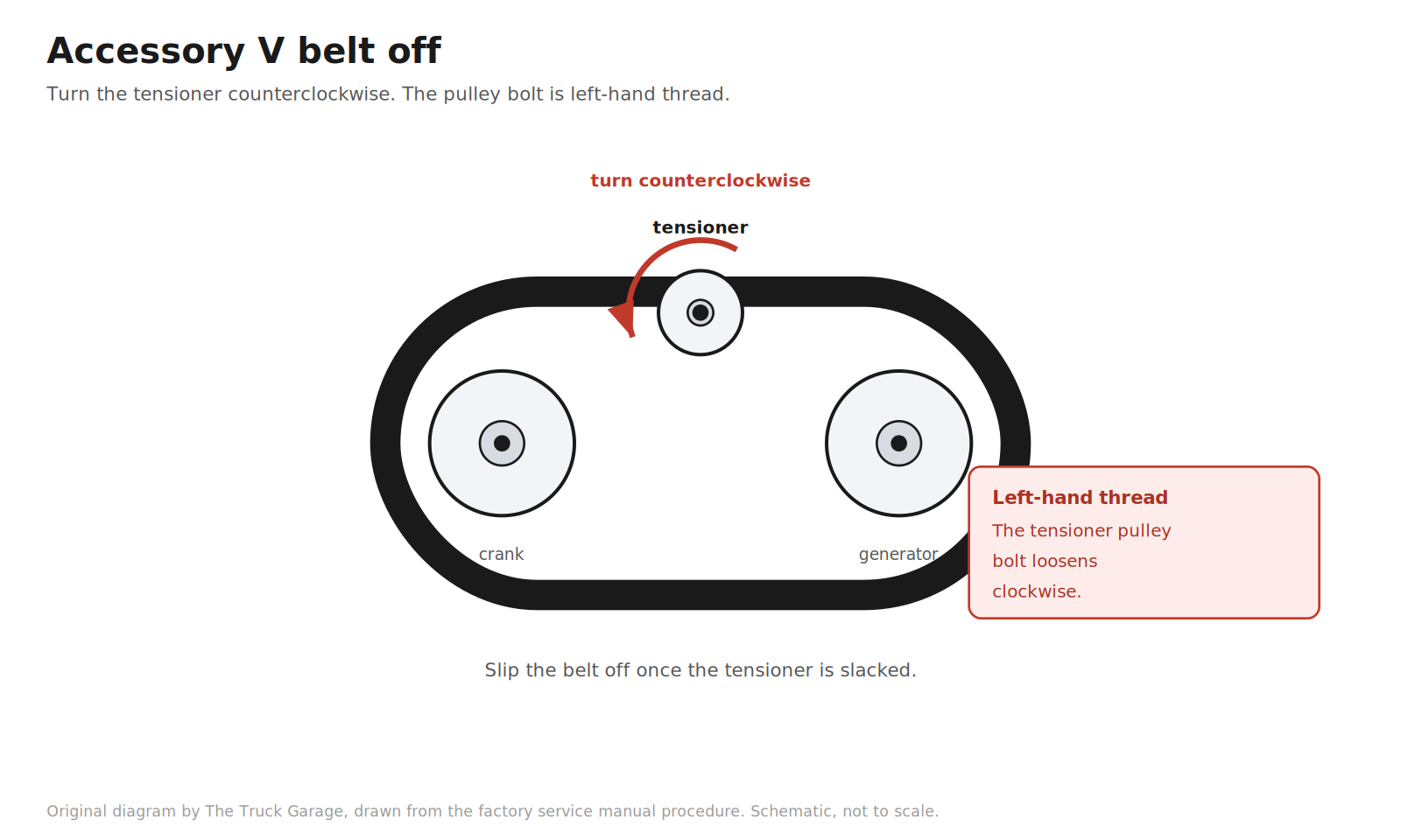
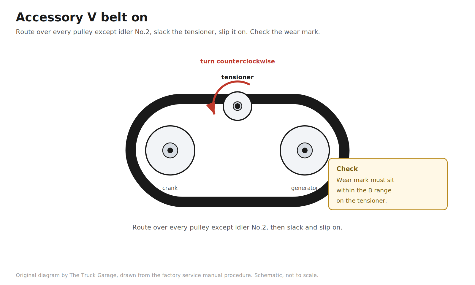
7. Remove the accessory (fan and generator) V belt. Turn the belt tensioner counterclockwise to slack the belt, then slip it off. Warning: the tensioner pulley bolt is left-hand thread. If you are replacing the belt anyway, this is when the old one comes off. [manual]
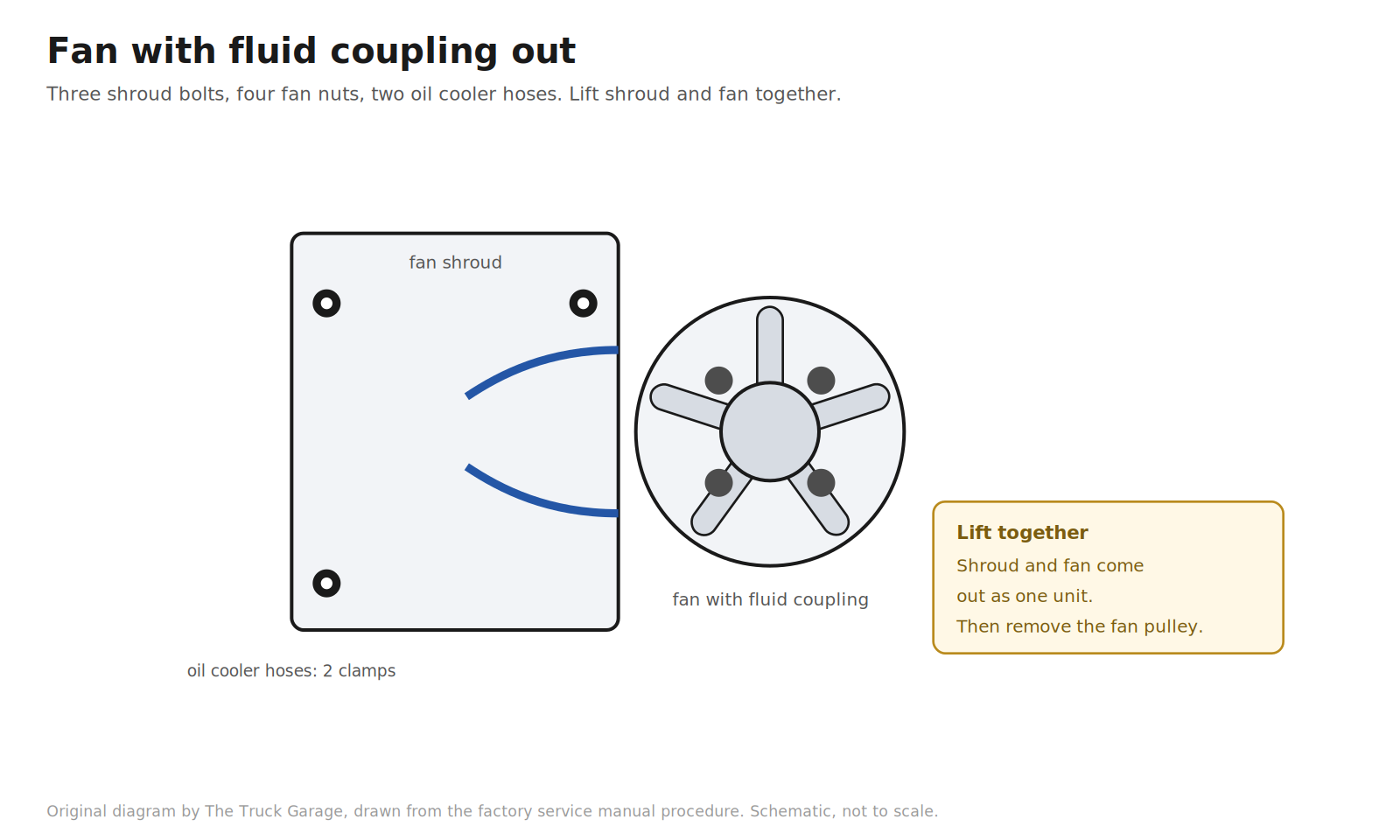
8. Remove the fan with fluid coupling. Unfasten each clip and the two hose clamps, and separate the two oil cooler hoses from the fan shroud. Remove the three bolts holding the fan shroud to the radiator. Remove the four nuts holding the fan with fluid coupling to the engine. Lift the shroud and fan out together. Remove the fan pulley. [manual]
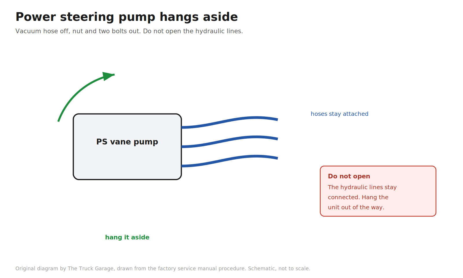
9. Separate the power steering vane pump. Disconnect the vacuum hose. Remove the nut and two bolts. Hang the pump aside with its hoses still attached. Do not open the hydraulic lines. [manual]
10. Remove the generator (alternator). [manual]
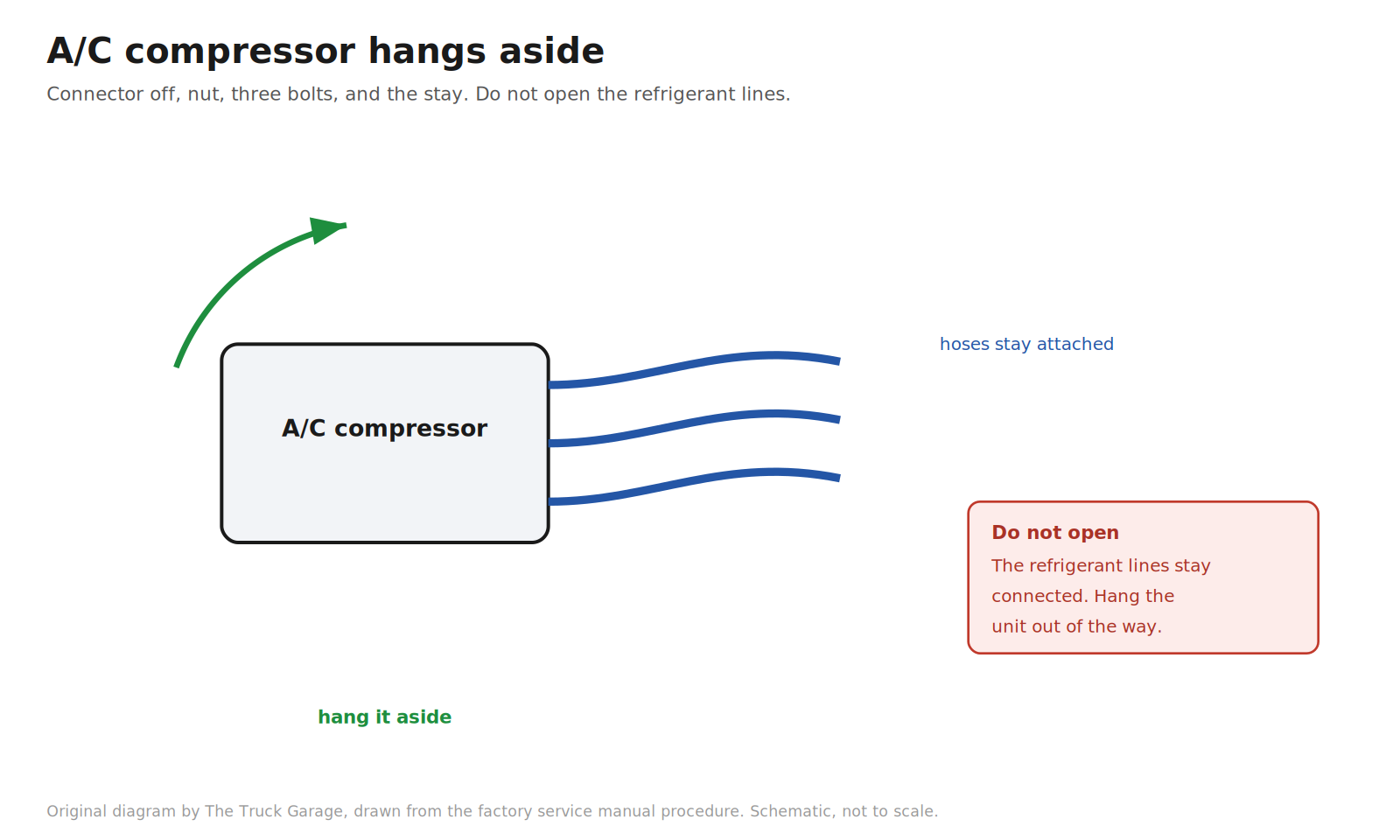
11. Separate the A/C compressor. Disconnect the compressor connector. Remove the nut, three bolts, and the compressor stay. Hang the compressor aside with its hoses still attached. Do not open the refrigerant lines. [manual]
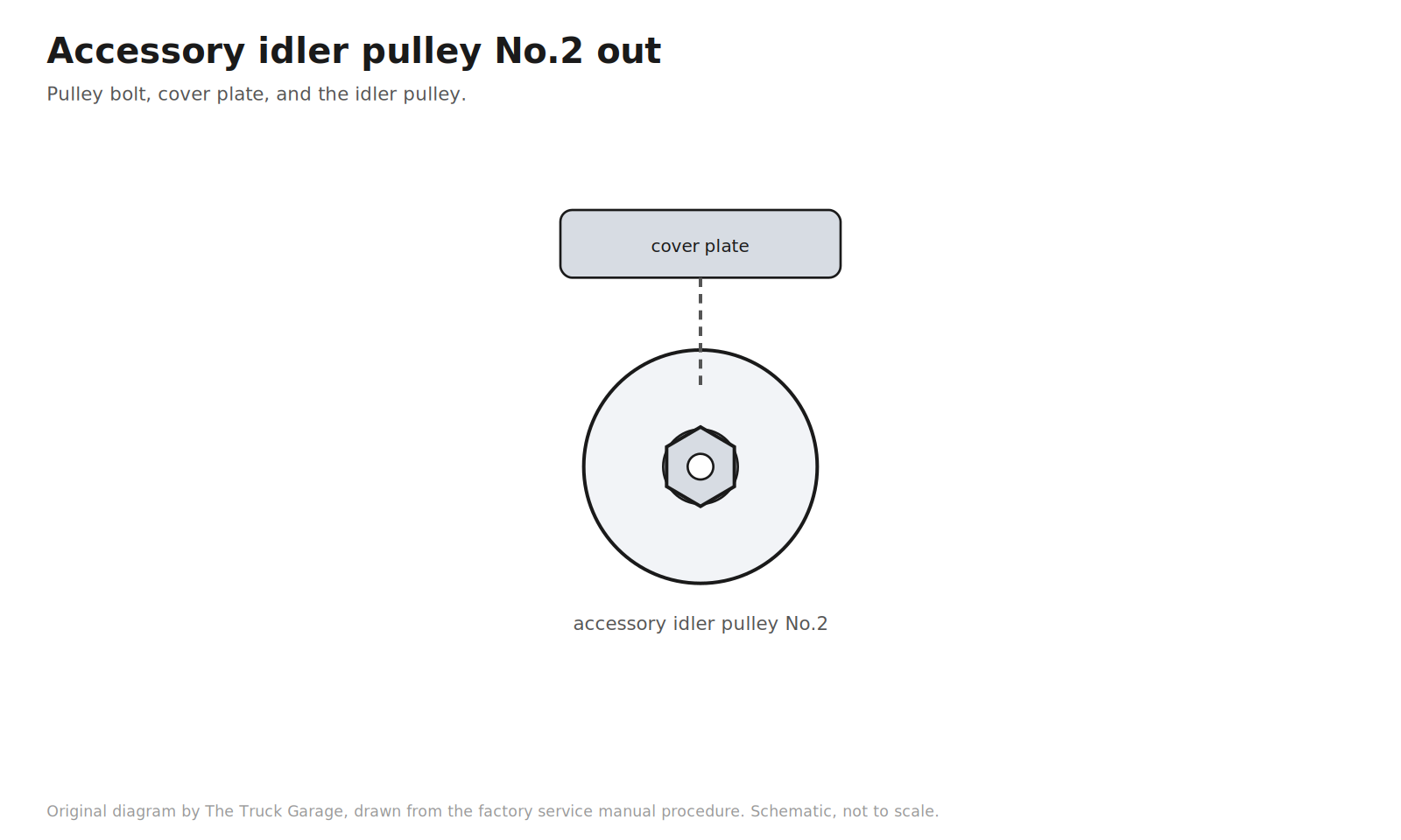
12. Remove the accessory idler pulley No.2. Remove the pulley bolt, the cover plate, and the idler pulley. [manual]
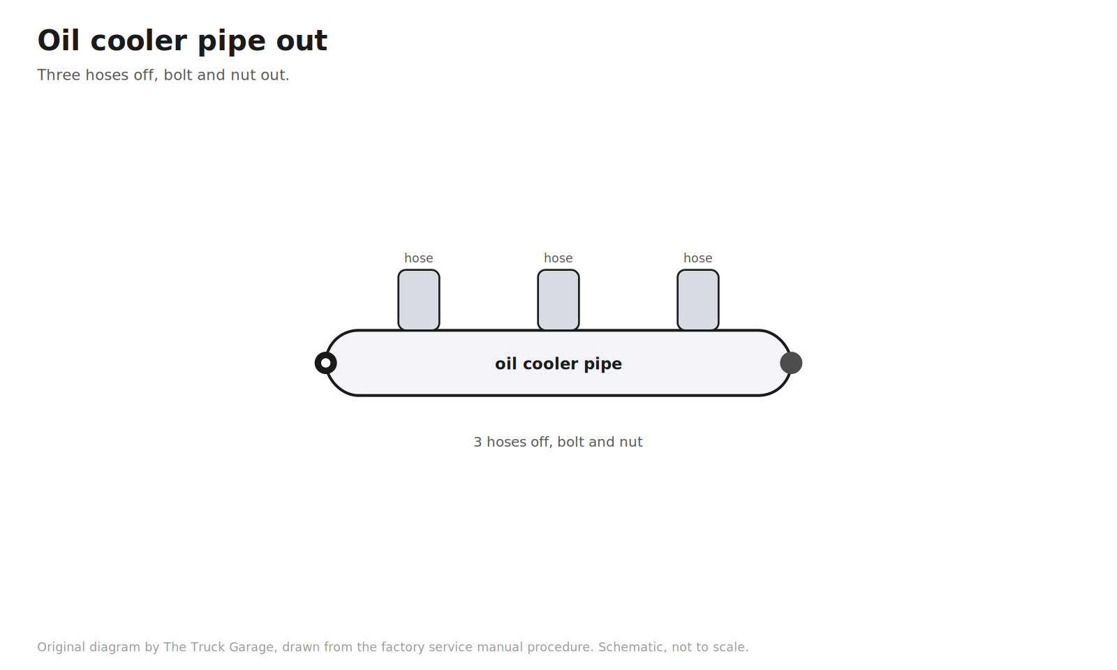
13. Remove the oil cooler pipe. Disconnect the three hoses. Remove the bolt and nut. [manual]
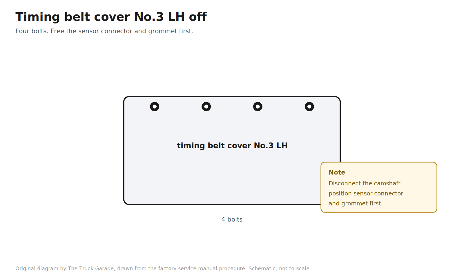
14. Remove the timing belt cover No.3 LH. Remove the grommet and separate the camshaft position sensor connector from the cover. Remove the four bolts and the cover. [manual]
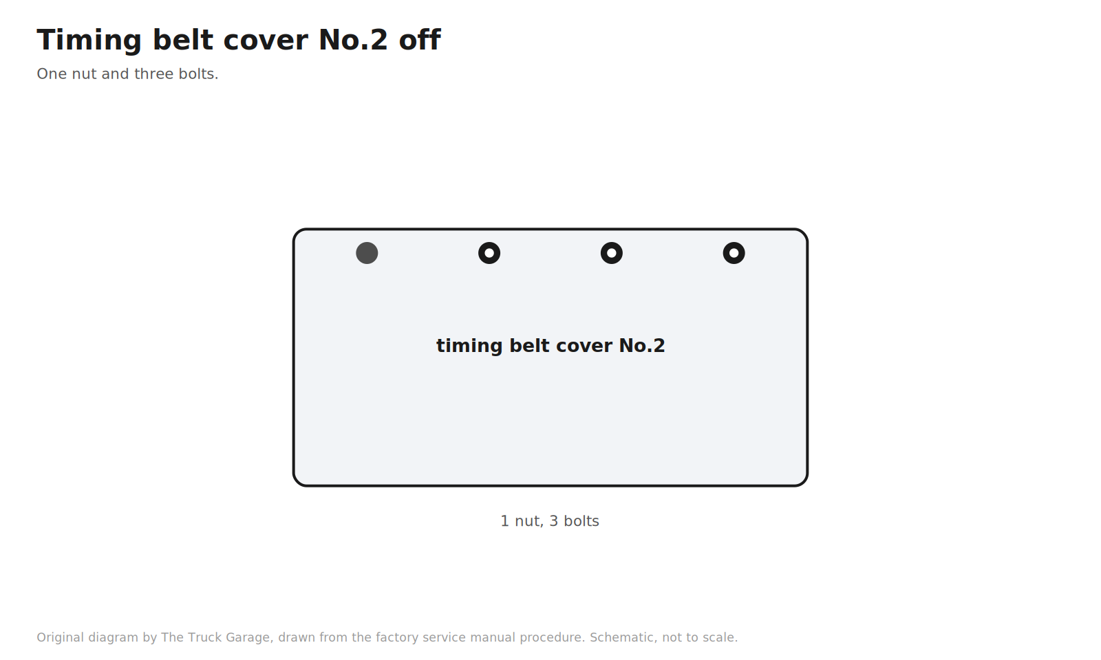
15. Remove the timing belt cover No.2. Remove the nut and three bolts. [manual]
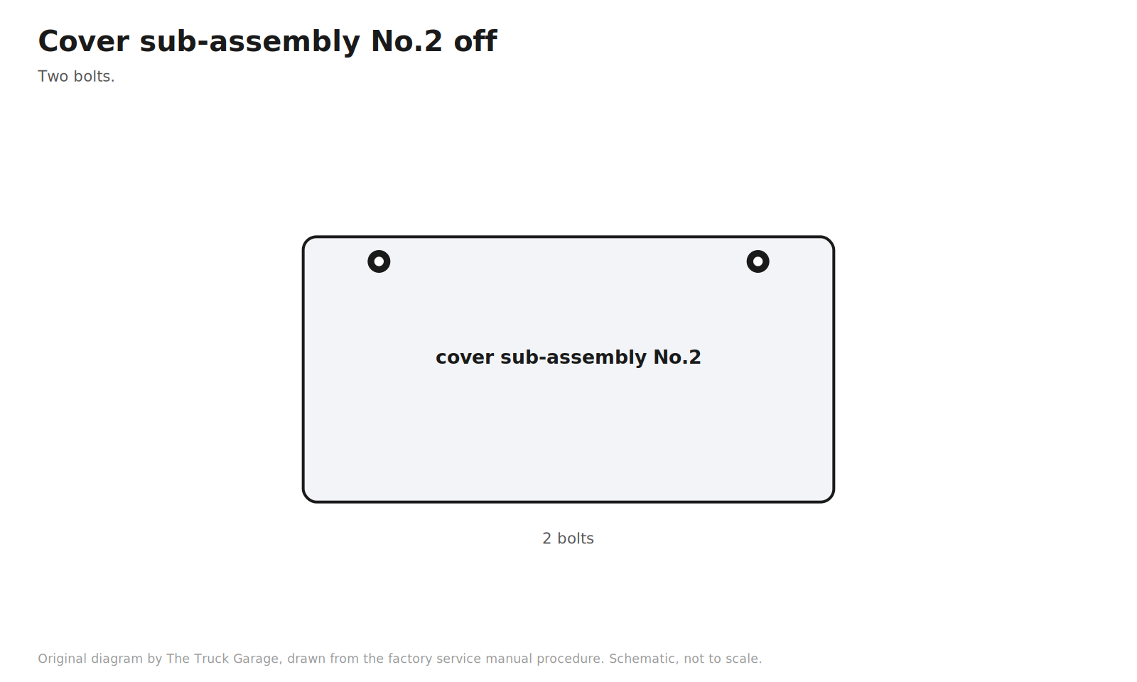
16. Remove the timing belt cover sub-assembly No.2. Two bolts. [manual]
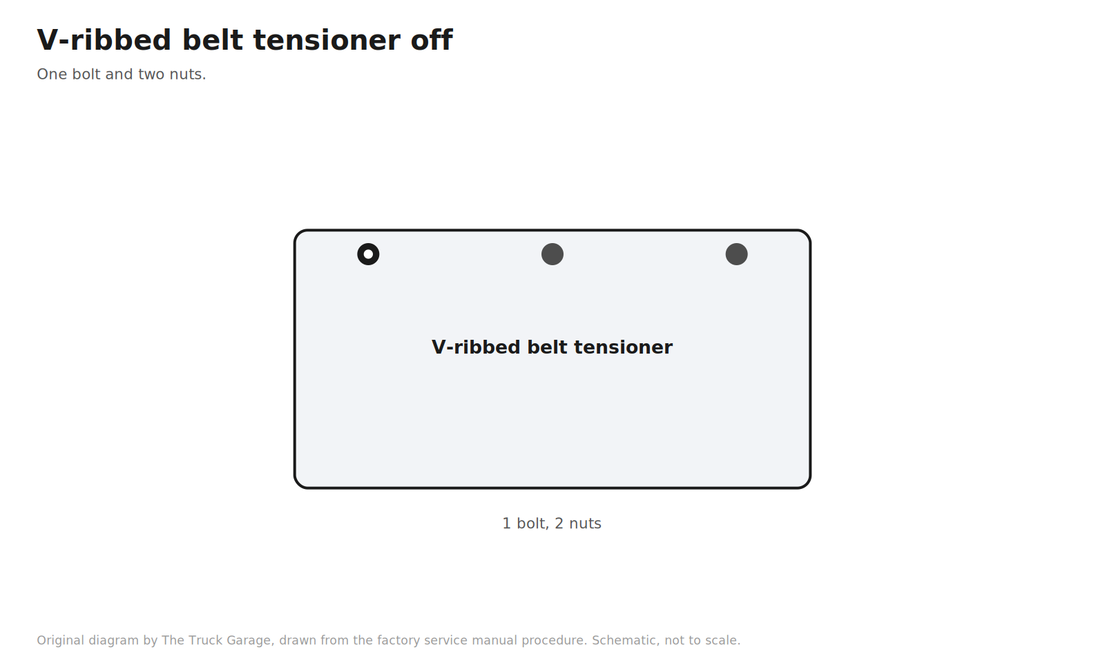
17. Remove the V-ribbed belt tensioner assembly. One bolt and two nuts. [manual]
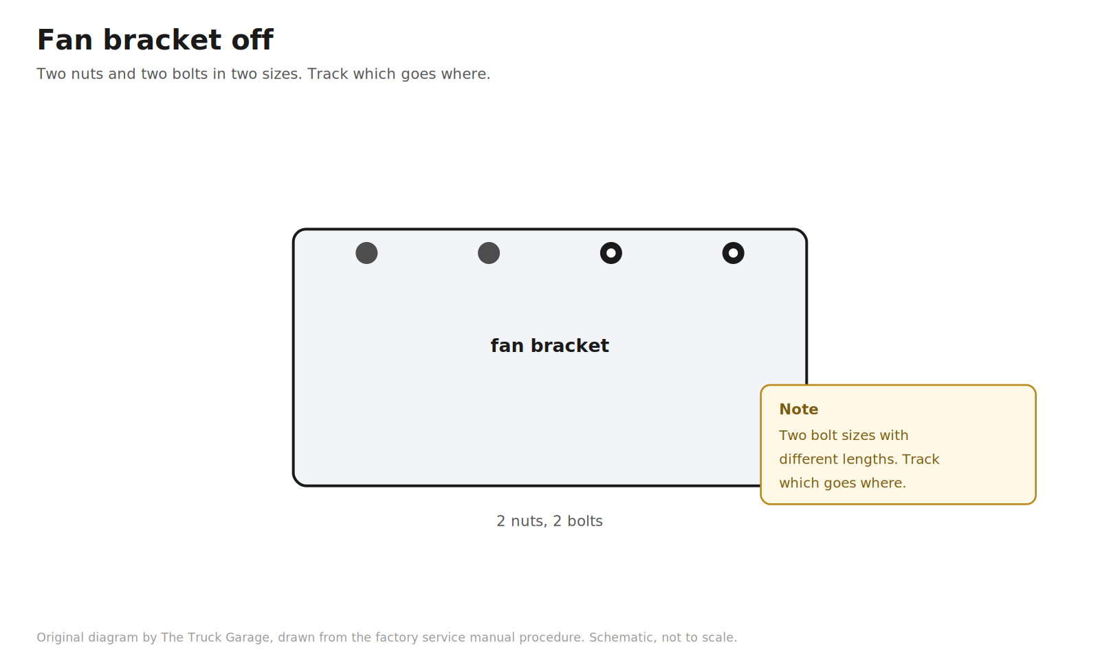
18. Remove the fan bracket. Two nuts and two bolts. Note that the factory uses two bolt sizes here, with different lengths. Keep track of which goes where. [manual]
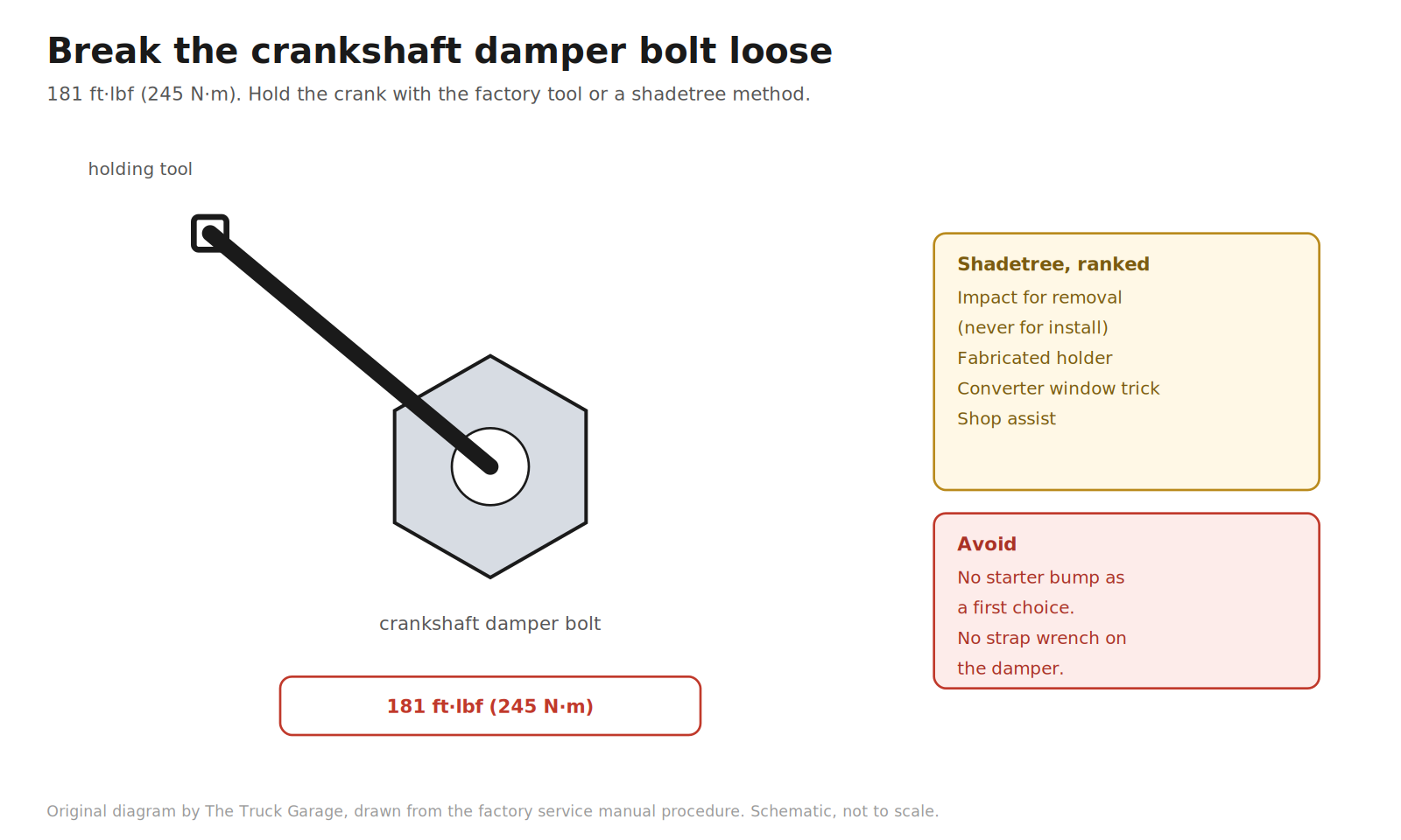
19. Remove the crankshaft damper bolt. This is the gatekeeper of the job. The factory tool is the crankshaft pulley holding tool (SST 09213-70011) with the companion flange holding tool. The bolt is torqued to 181 ft·lbf (245 N·m), so breaking it loose takes real leverage. [manual] Shadetree, ranked by sanity:
- Electric impact for removal. A modern 1/2 in brushless impact with 1,000+ ft·lbf of breakaway torque zips the bolt off. Never use the impact to install the bolt. [community]
- Fabricated holder. Flat steel bar with two holes drilled to match the pulley bolt holes, braced against the ground or frame. Cheap, controlled, safe if built stout. [community]
- Torque converter window trick. Pull the transmission inspection cover, seat a deep socket on a torque converter bolt, and rotate until it jams against the bell housing. Free. Keep the socket straight and fully seated. [community]
- Shop assist. Have a shop crack the bolt loose, drive home gently, and do the job. Have them torque it to spec afterward if you cannot. [community]
- Do not lead with the starter bump. Breaker bar against the frame, bump the starter. Owners have snapped 1/2 in breaker bars doing this. Last resort only. [community]
- Do not use a strap wrench on the damper. It can damage the pulley. [community]
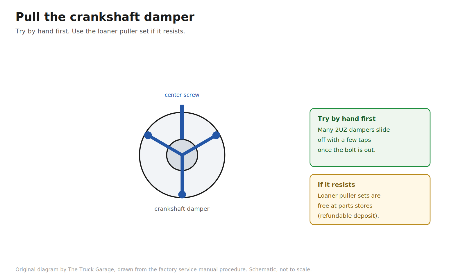
20. Pull the crankshaft damper. The factory puller is SST 09950-50013. [manual] Shadetree: parts stores loan harmonic balancer puller sets free with a refundable deposit. Many owners report the 2UZ damper slides off by hand with a few taps once the bolt is out, so try that before rigging the puller. [community]
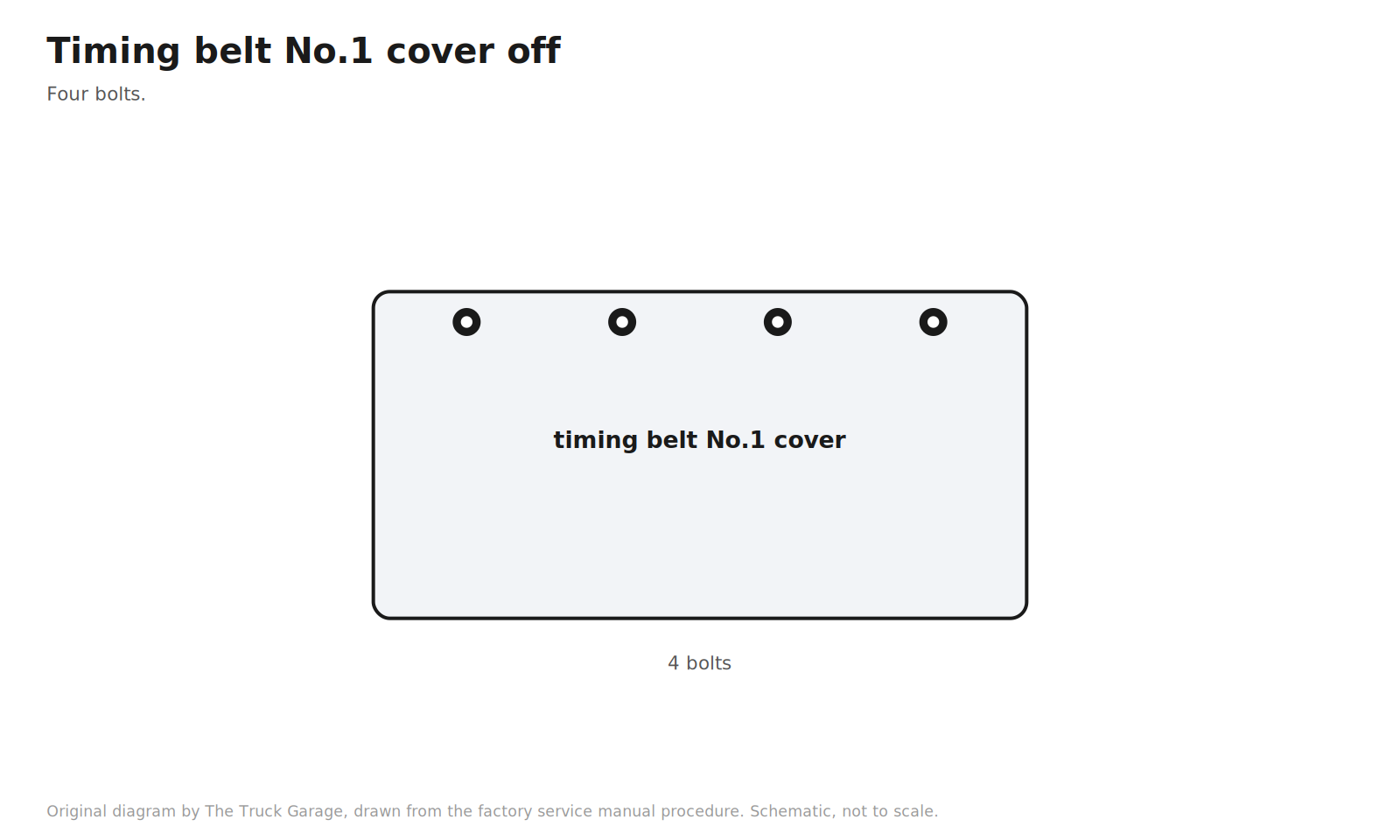
21. Remove the timing belt No.1 cover. Four bolts. [manual]
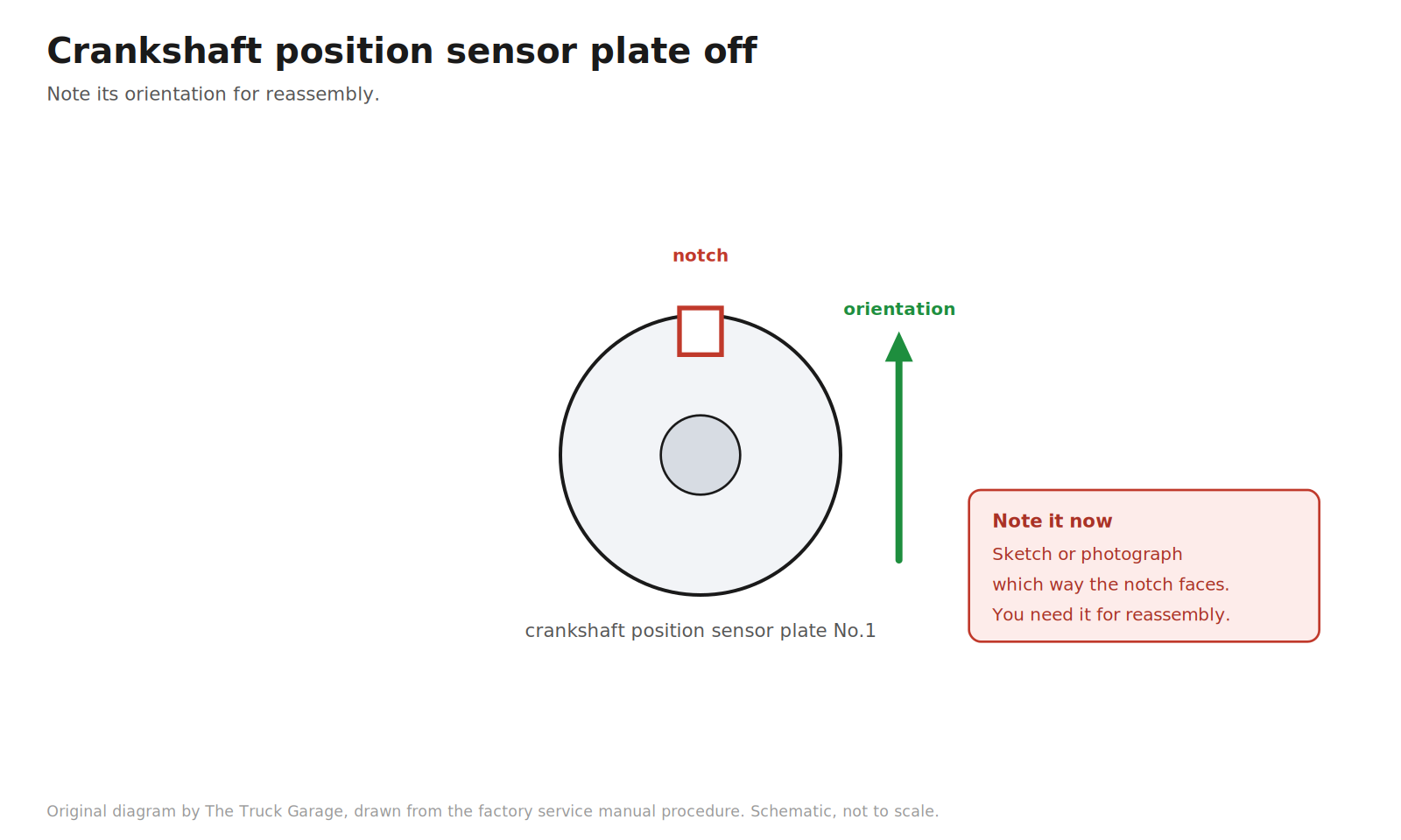
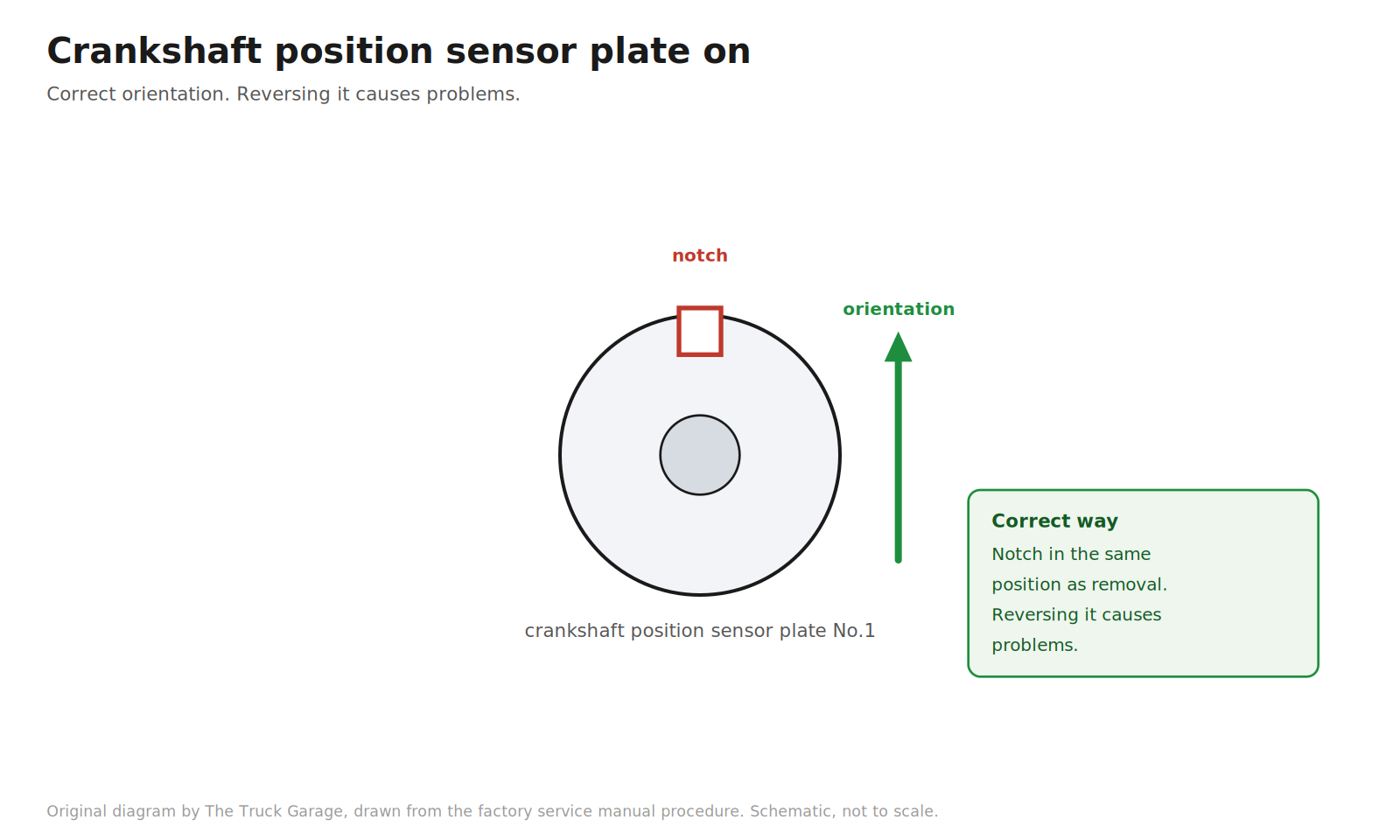
22. Remove the crankshaft position sensor plate No.1. Note its orientation for reassembly. [manual]
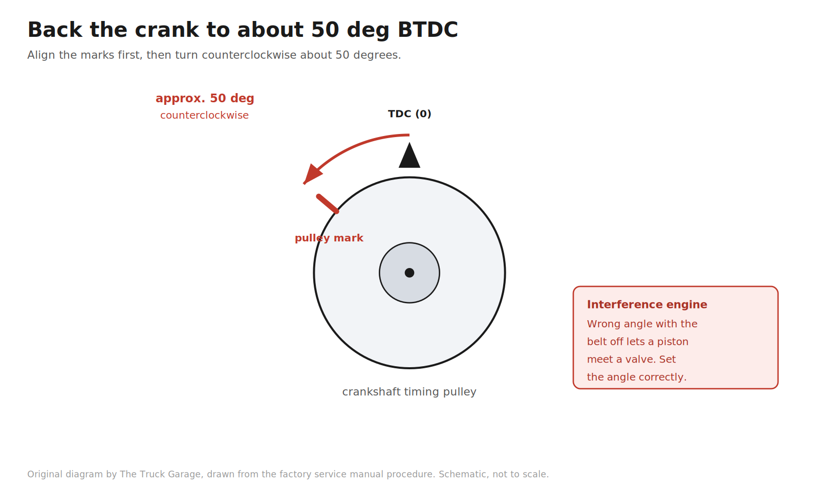
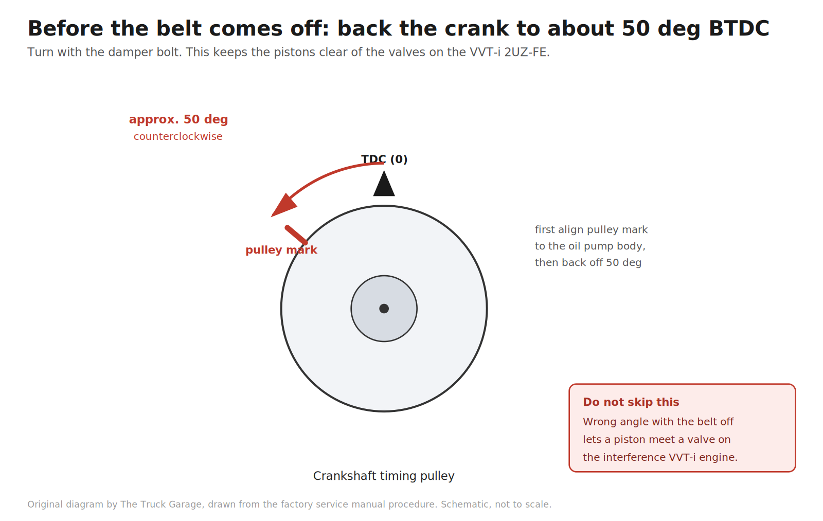
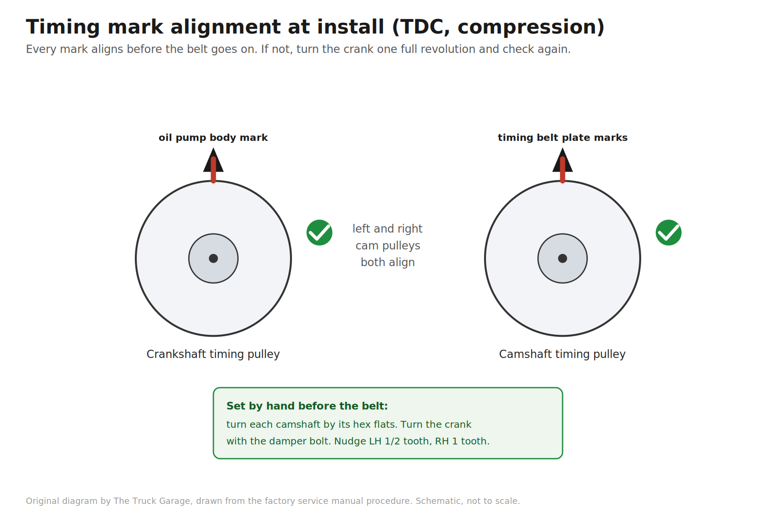
23. Set the crankshaft to approximately 50 degrees before top dead center. This is the interference-engine safety step. Turn the crankshaft with the damper bolt to align the timing marks of the crankshaft timing pulley with the oil pump body. Check that the timing marks of the camshaft timing pulleys align with the timing belt plates. If they do not, turn the crankshaft one full revolution (360 degrees) and check again. Then turn the crankshaft counterclockwise approximately 50 degrees. [manual] Warning: with the belt disengaged, having the crankshaft at the wrong angle can let a piston head contact a valve head when the camshaft timing pulley is disturbed. Set the angle correctly. [manual]
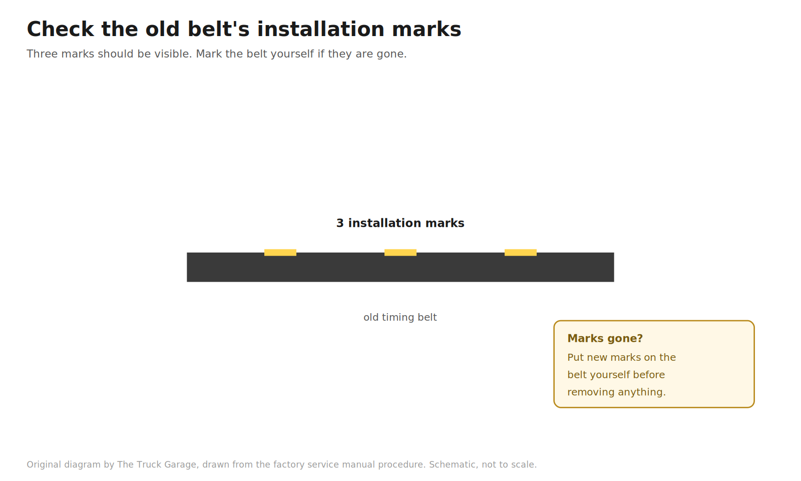
24. If you are reusing the old belt, check its installation marks. Turn the crankshaft and confirm three installation marks on the belt. If the marks have disappeared, put new marks on the belt before removing anything. In practice you are installing a new belt from the kit, so this step is just confirming the old belt’s marks for reference. [manual]
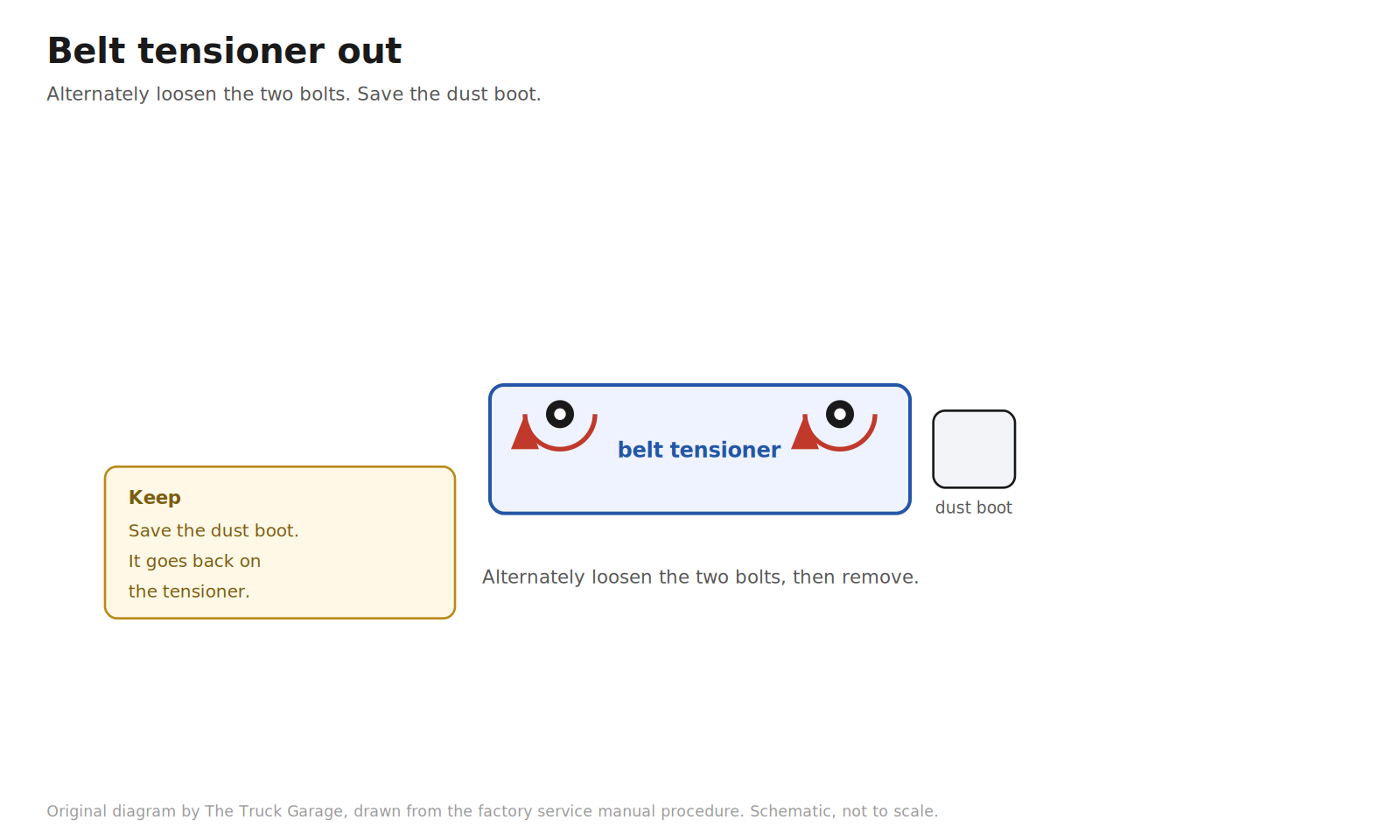
25. Remove the belt tensioner. Alternately loosen the two bolts, then remove the bolts, the tensioner, and the dust boot. [manual]
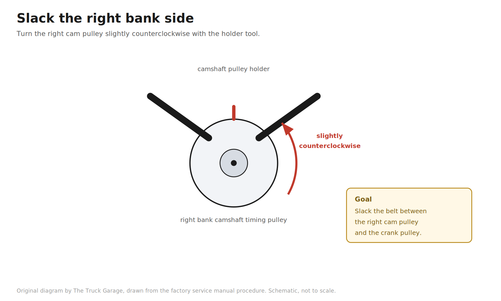
26. Slack the right bank side. Using the camshaft pulley holder (SST 09960-10010), turn the right bank camshaft timing pulley slightly counterclockwise. This loosens the belt tension between the right cam pulley and the crank pulley. [manual]
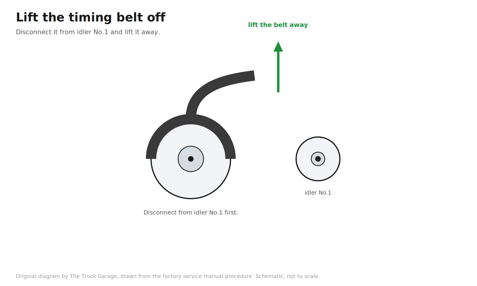
27. Remove the timing belt. Disconnect the belt from timing belt idler No.1 and lift the belt off. [manual]
Belt and pump replacement
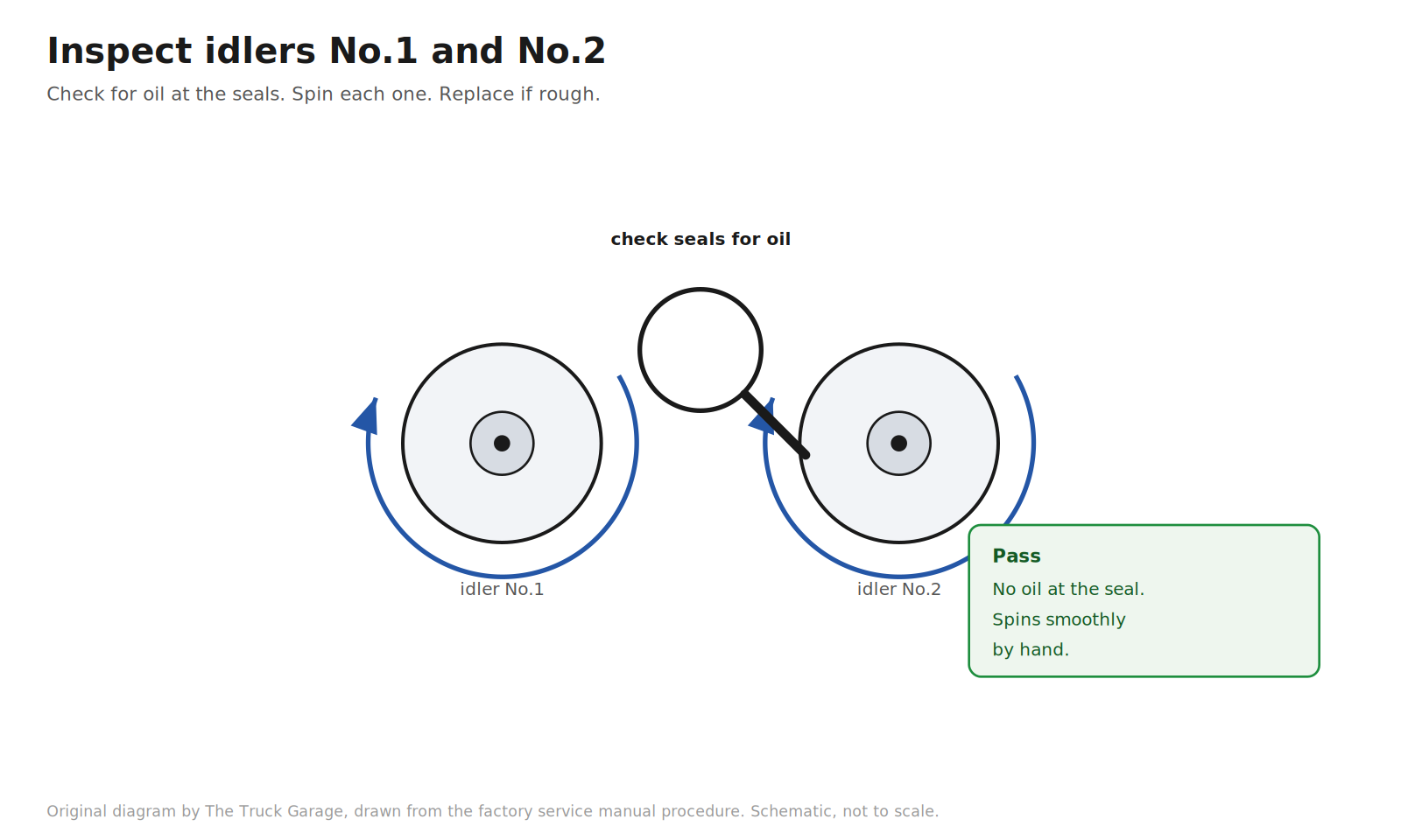
28. Inspect the timing belt idlers No.1 and No.2. Visually check the seal area of each idler pulley for oil leakage. Spin each idler by hand and confirm it turns smoothly. Replace any idler that leaks or feels rough. New idlers come in the kit. [manual]
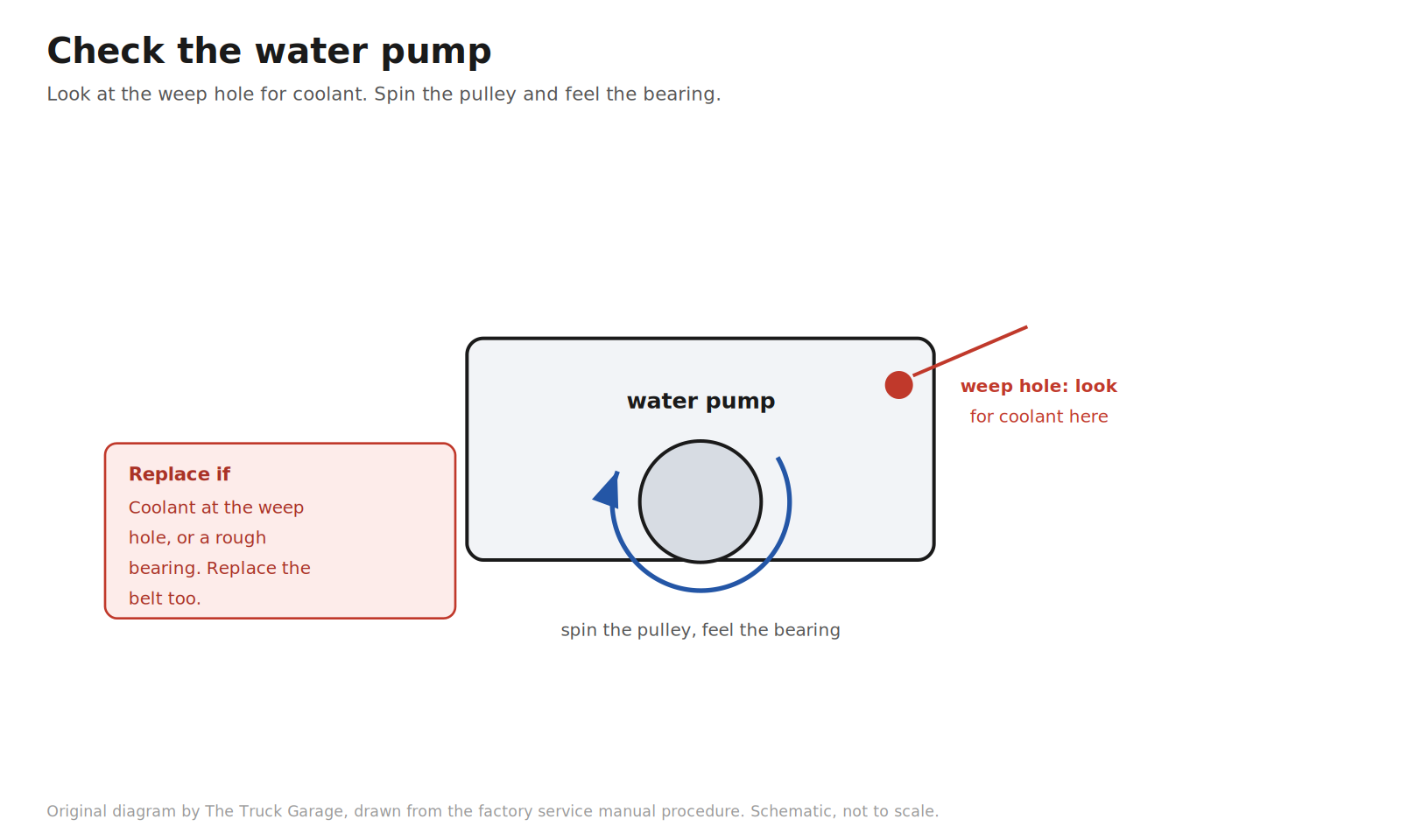
29. Check the water pump. Look at the pump’s air hole and drain (weep) hole for coolant leakage. Turn the pulley and confirm the bearing moves smoothly. If leakage is found, replace the water pump and the timing belt. If the bearing feels rough, replace the pump. [manual]
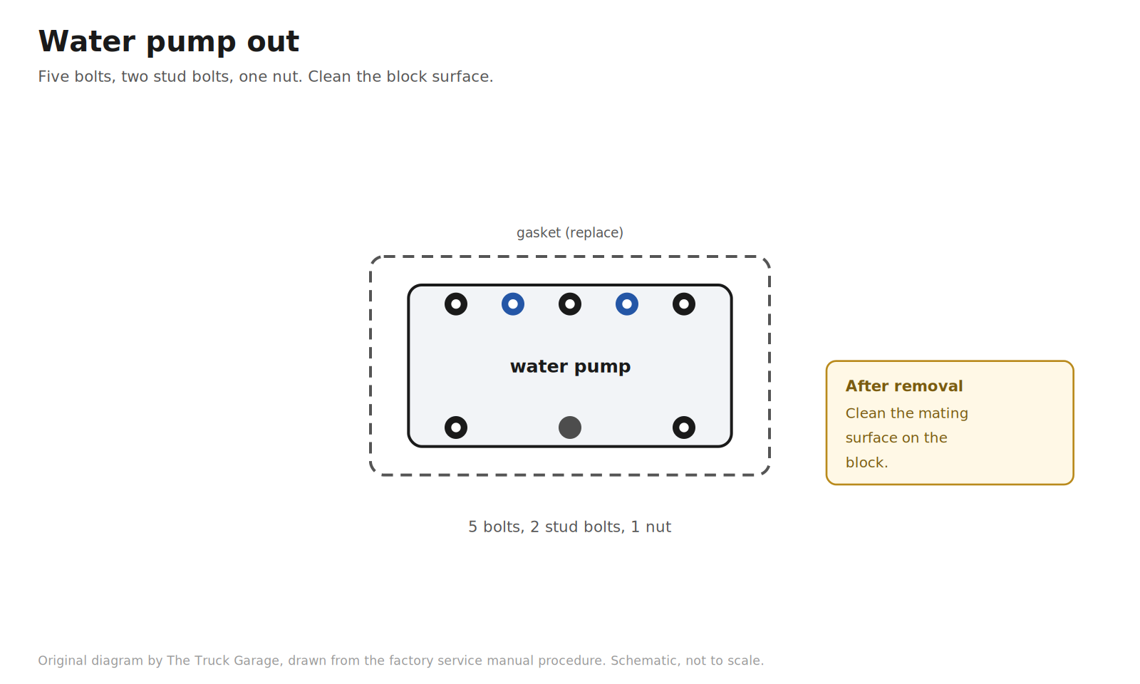
30. Remove the water pump. Remove the five bolts, two stud bolts, nut, water pump, and gasket. Clean the mating surface on the block. [manual]
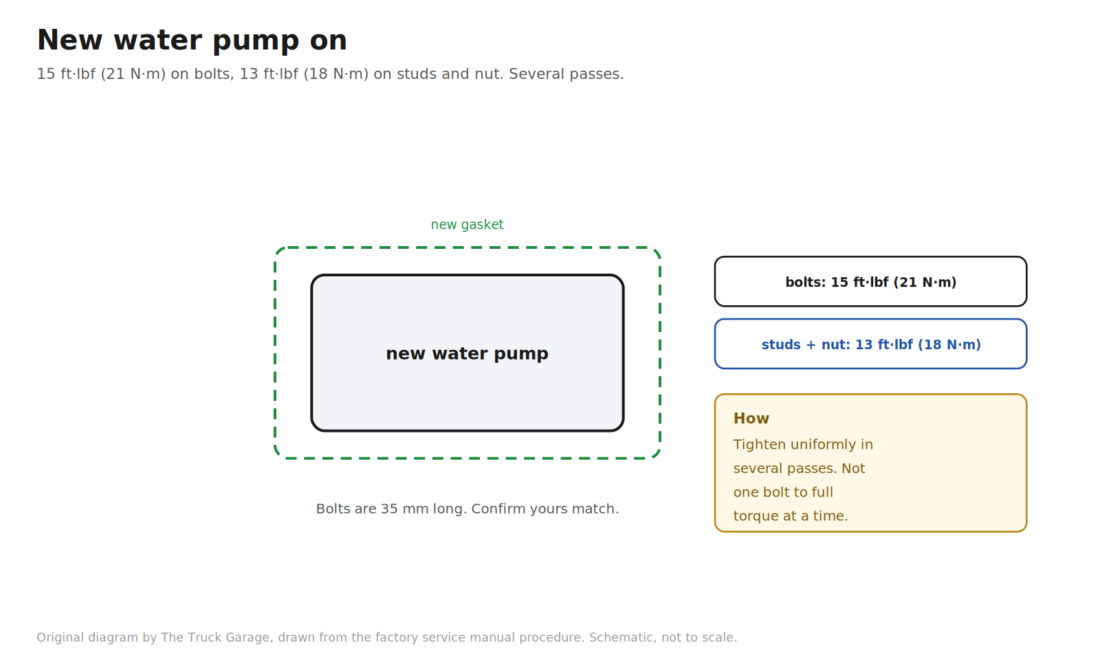
31. Install the new water pump. Fit the new gasket and the pump with the five bolts, two stud bolts, and nut. Tighten them uniformly in several passes, not one bolt at a time to full torque. Torque: bolts 15 ft·lbf (21 N·m); stud bolts and nut 13 ft·lbf (18 N·m). The factory notes the bolts are 35 mm long, so confirm your bolts match. [manual]
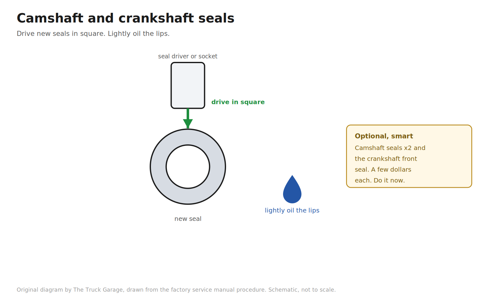
32. Replace the camshaft seals and crankshaft front seal (optional, recommended). With the belt off and the pulleys exposed, the seals are right there. Pull the old seals, drive the new ones in square with a seal driver or a suitable socket, and lightly oil the seal lips. They cost a few dollars each and you do not want to open this up again for a five dollar seal. [community]
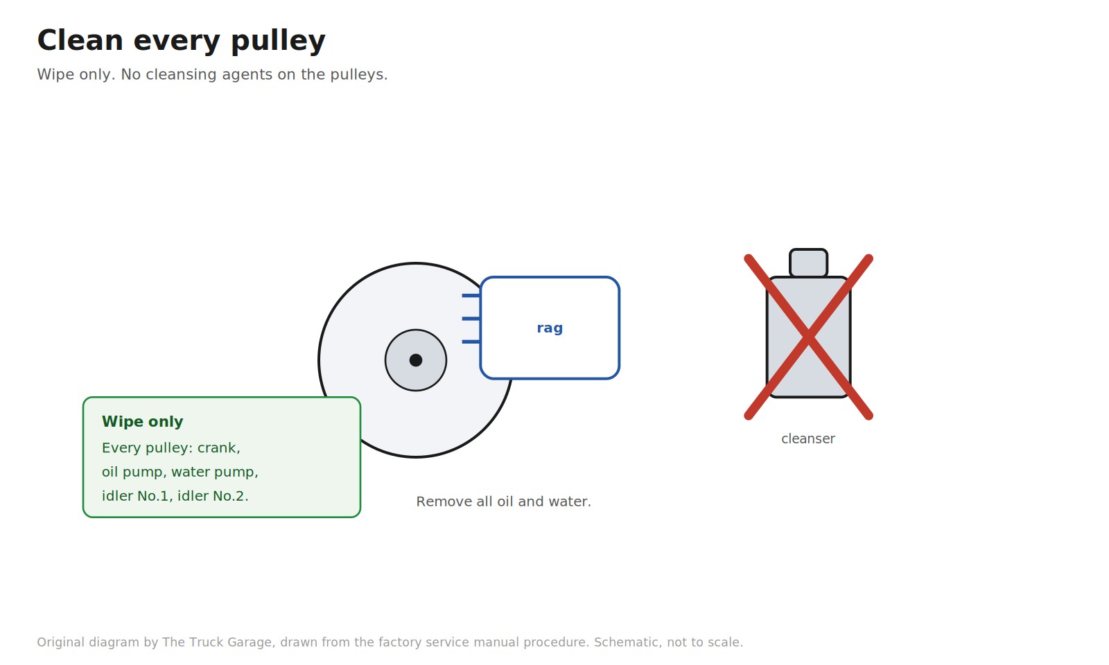
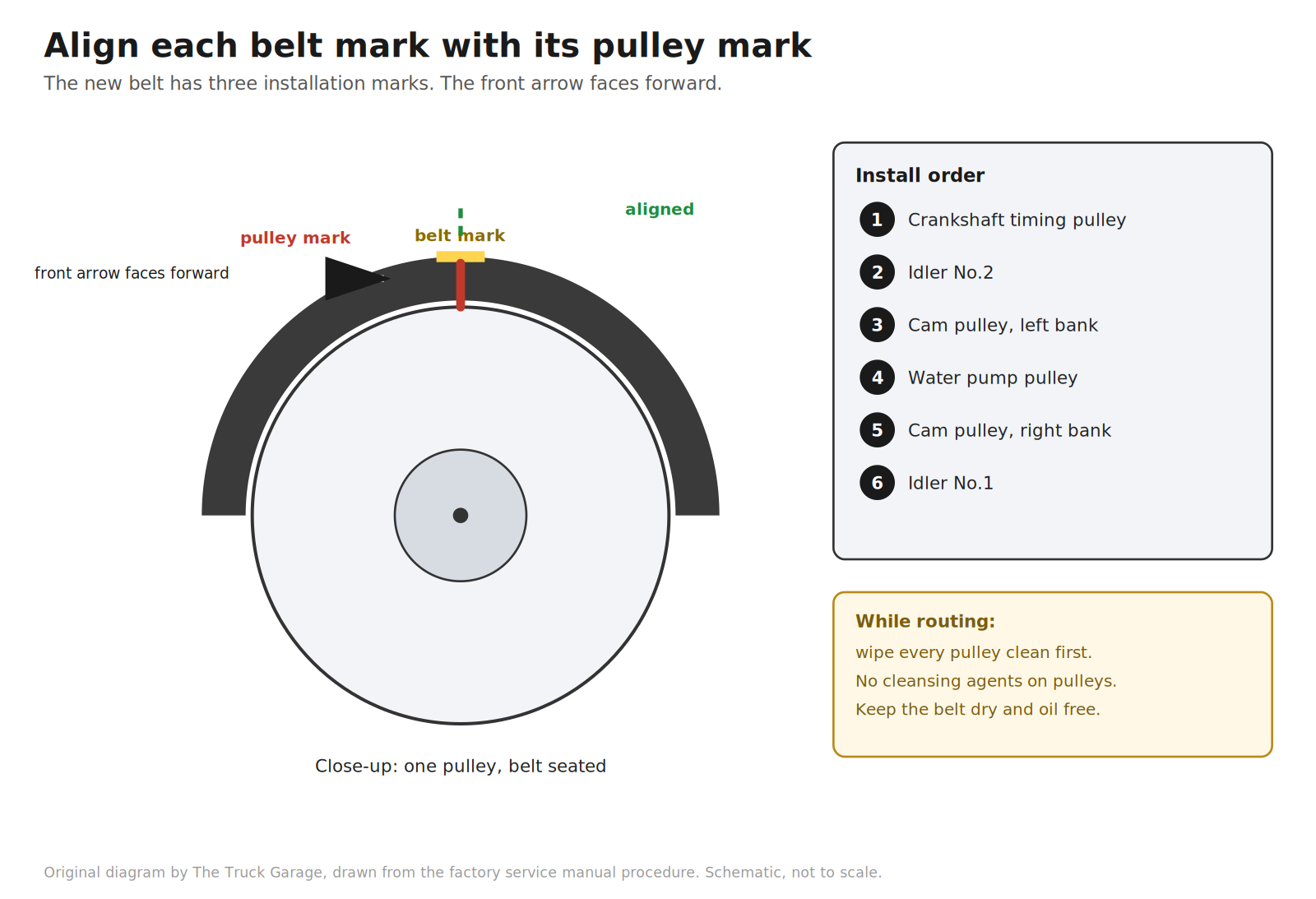
33. Clean every pulley. Wipe the crankshaft pulley, oil pump pulley, water pump pulley, idler No.1, and idler No.2 to remove all oil and water. The factory is explicit: wipe only. Do not use any cleansing agent on the pulleys. [manual]
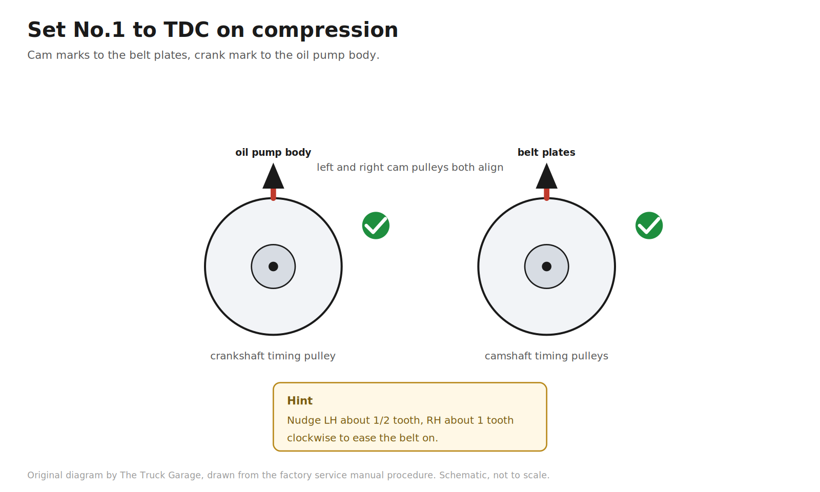
34. Set No.1 cylinder to top dead center on compression. Turn each camshaft by its hexagonal portion to align the timing marks of the camshaft timing pulleys with the timing belt plates. The manual’s hint: turning the left bank pulley about half a tooth clockwise and the right bank pulley about one tooth clockwise makes the belt installation easier. Then turn the crankshaft with the damper bolt to align the timing marks of the crankshaft timing pulley with the oil pump body. [manual]
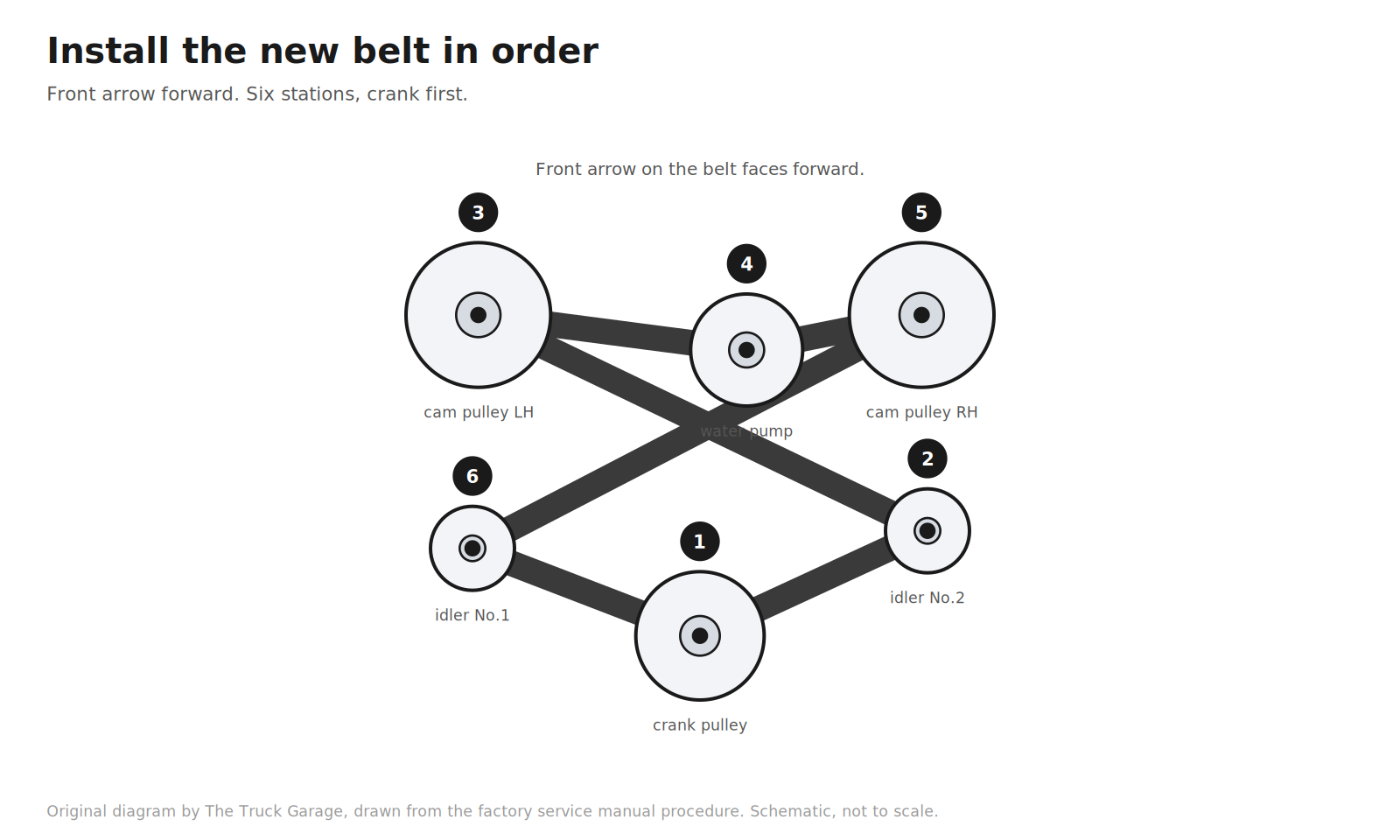
35. Install the new timing belt, in order. Face the front mark (arrow) on the belt forward. Put the belt on in this sequence, aligning each installation mark on the belt with the timing mark of its pulley: crankshaft timing pulley, idler No.2, left bank camshaft timing pulley, water pump pulley, right bank camshaft timing pulley, idler No.1. [manual]

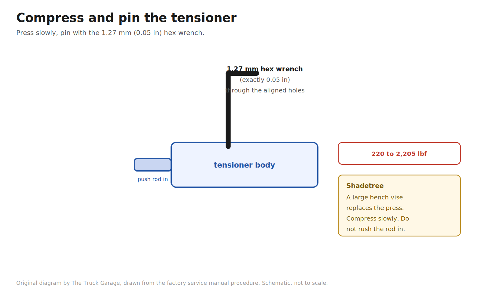
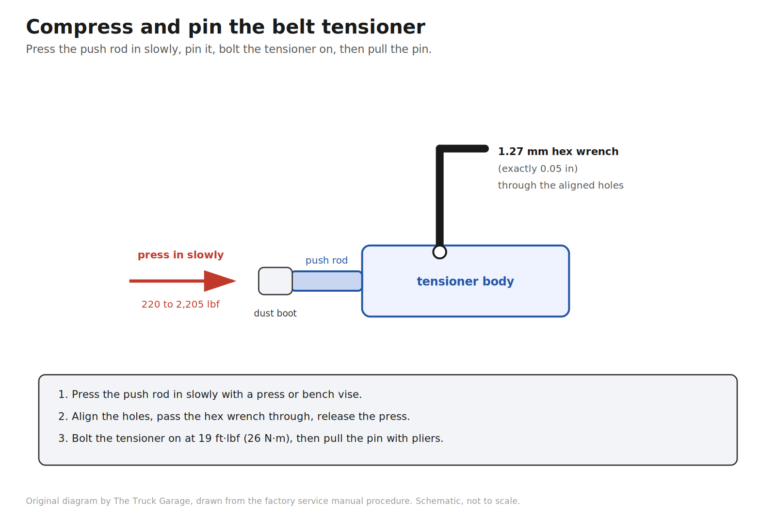
36. Compress and pin the belt tensioner. Using a press, slowly press the push rod in with 220 to 2,205 lbf of pressure. Align the holes in the push rod and the housing, and pass the 1.27 mm (0.05 in) hex wrench through the holes to hold the push rod in the compressed position. Release the press. Fit the dust boot onto the tensioner. [manual] Shadetree: a large bench vise does the same job as the press. Compress slowly. Do not rush the push rod in. [community]
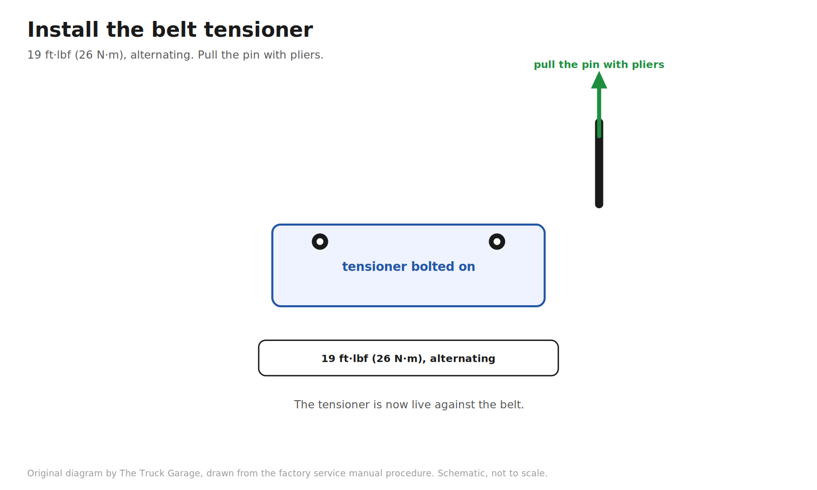
37. Install the belt tensioner. Temporarily install the tensioner with the two bolts, then alternately tighten the bolts to 19 ft·lbf (26 N·m). Using pliers, pull the 1.27 mm hex wrench out. The tensioner is now live against the belt. [manual]
Reassembly
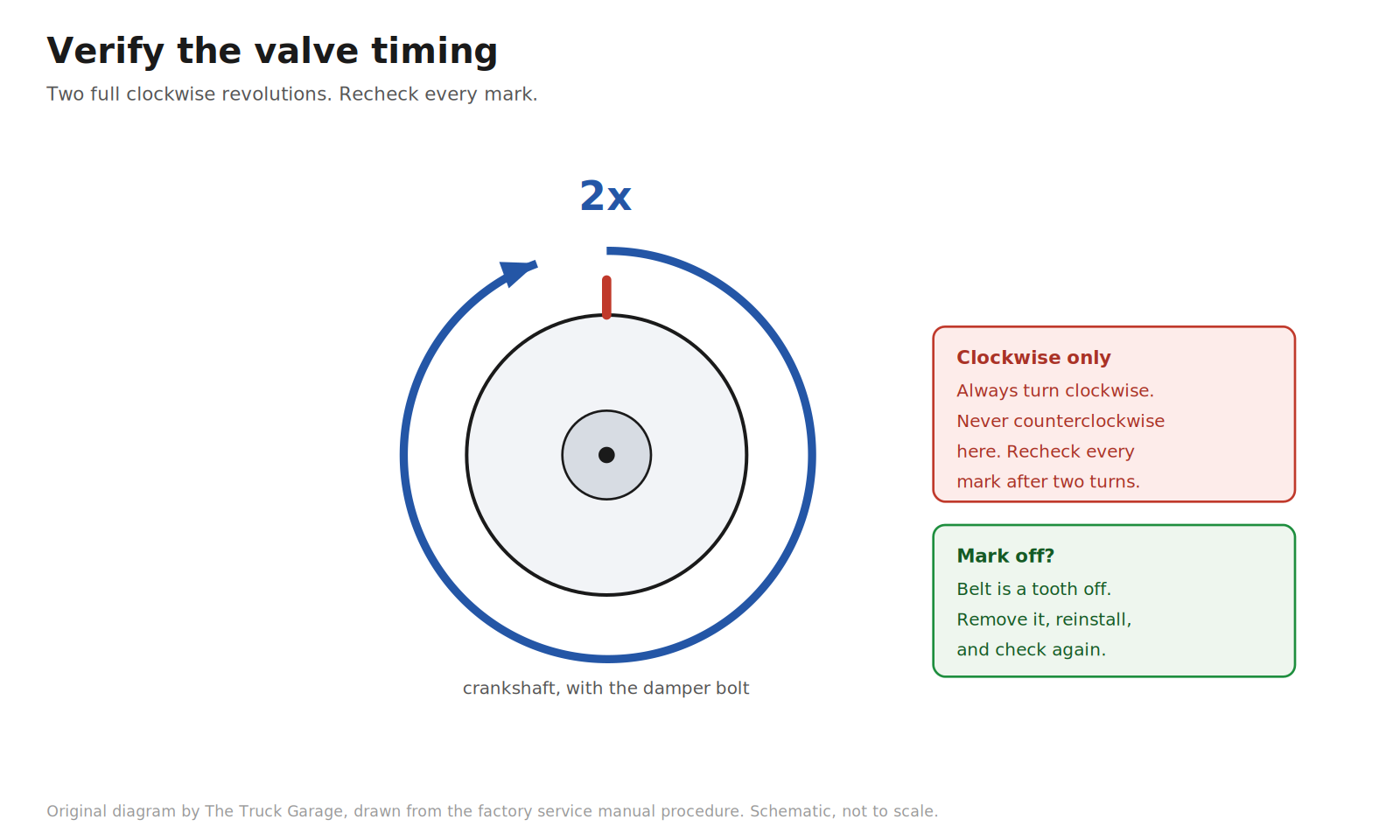
38. Verify the valve timing. Using the crankshaft damper bolt, slowly turn the crankshaft two full revolutions, from TDC back to TDC. Always turn clockwise. Never turn it counterclockwise here. Then check that every pulley’s timing marks still align with their marks. If any mark is off, remove the belt and reinstall it. When the marks are correct, remove the crankshaft damper bolt. [manual]
39. Install the crankshaft position sensor plate No.1. Install it in the correct orientation. Reversing it causes problems. [manual]
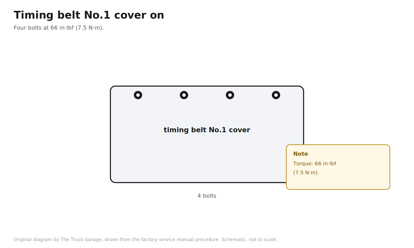
40. Install the timing belt No.1 cover. Four bolts, torqued to 66 in·lbf (7.5 N·m). [manual]
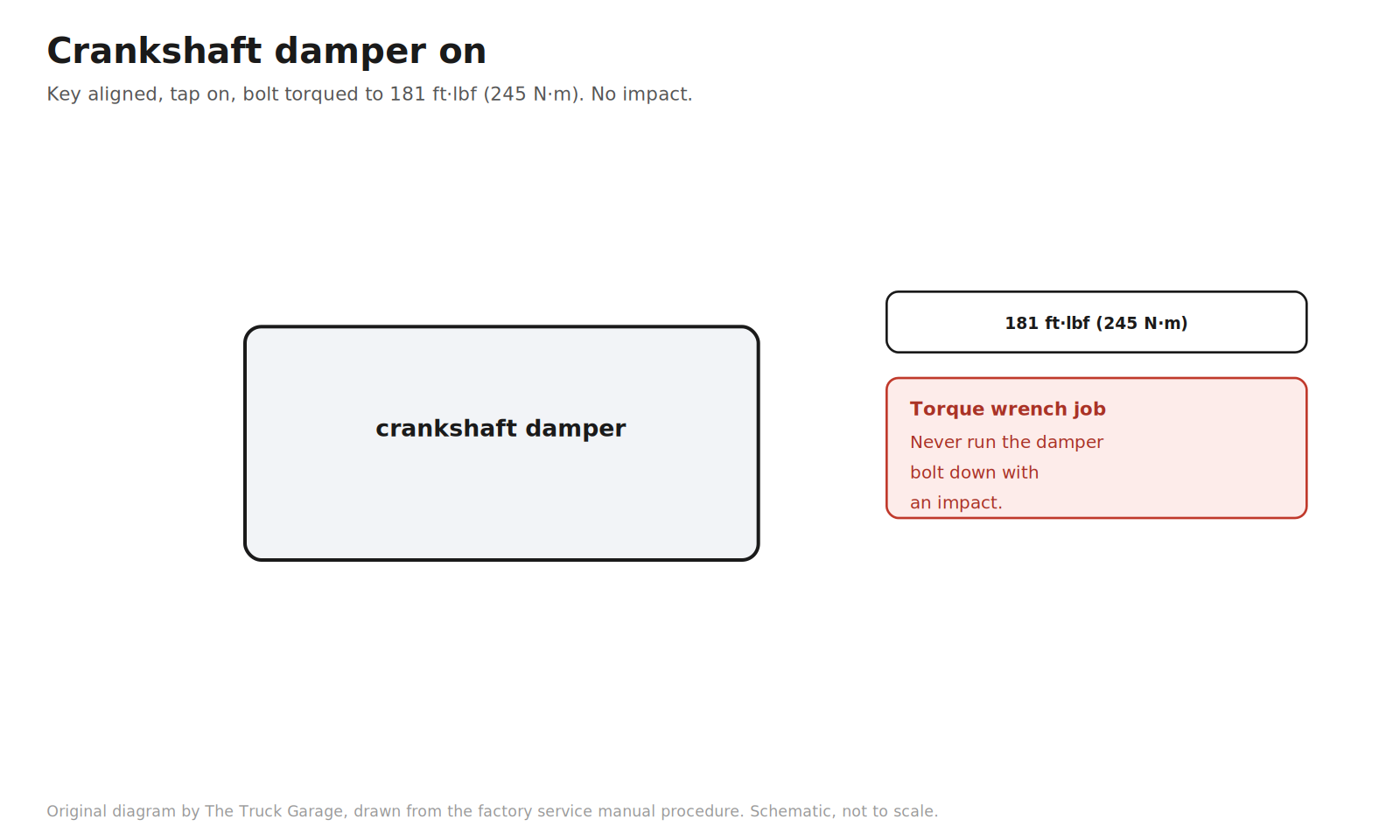
41. Install the crankshaft damper. Align the pulley set key with the key groove of the damper. Tap the damper on with a hammer using the proper driver. Install the damper bolt using the holding tool and torque it to 181 ft·lbf (245 N·m). This is a torque wrench job. Never run the bolt down with an impact. [manual]
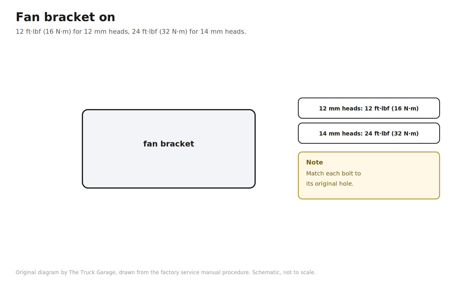
42. Install the fan bracket. Two bolts and two nuts. Torque to 12 ft·lbf (16 N·m) for the 12 mm head bolts, or 24 ft·lbf (32 N·m) for the 14 mm head bolts. Match each bolt to its original hole. [manual]
43. Install the V-ribbed belt tensioner. Bolt and two nuts, torqued to 11 ft·lbf (16 N·m). [manual]
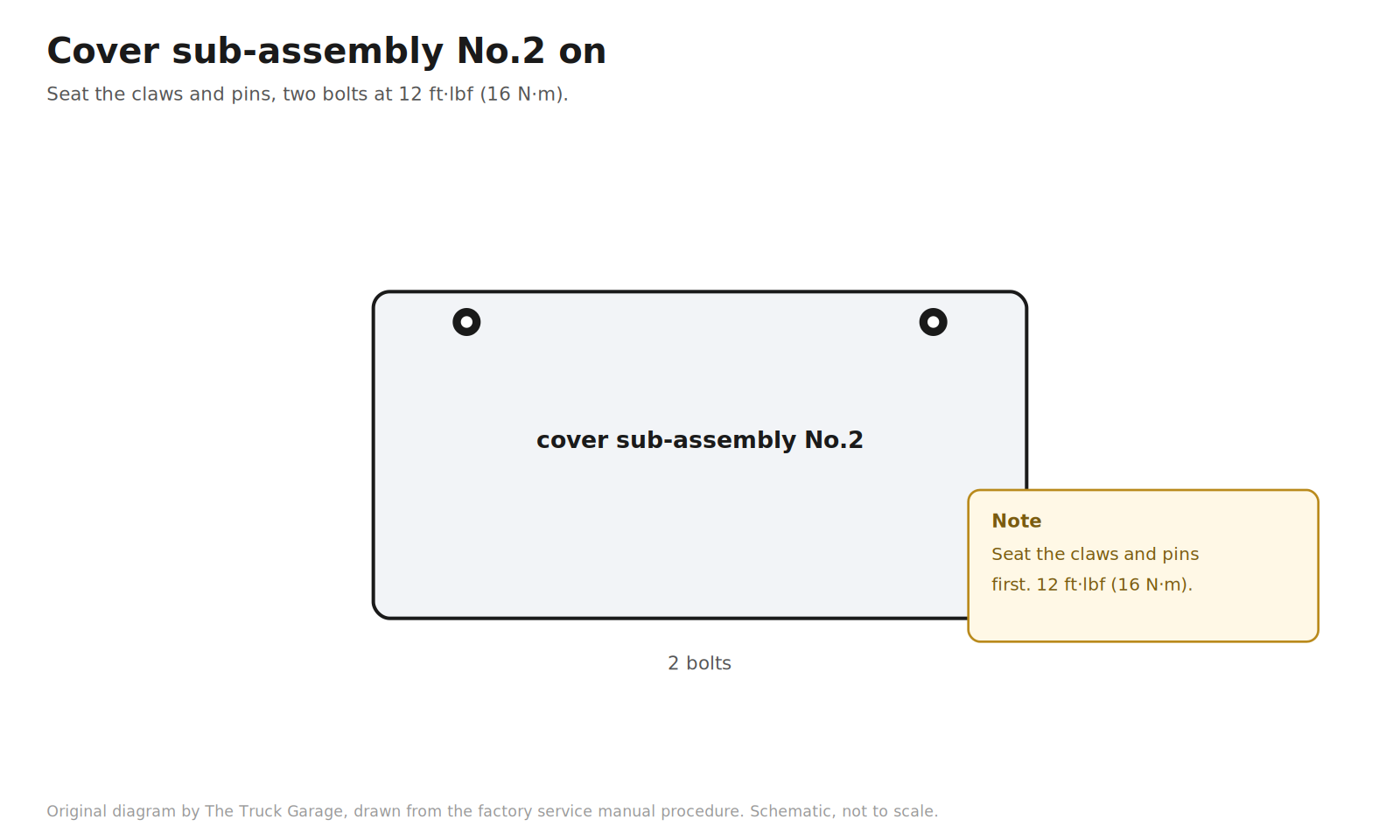
44. Install the timing belt cover sub-assembly No.2. Fit the cover so the claws and pins seat into their mating parts, then install the two bolts and torque to 12 ft·lbf (16 N·m). [manual]
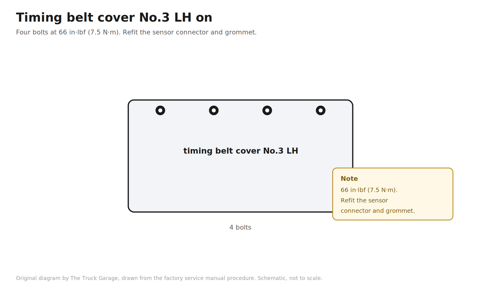
45. Install the timing belt cover No.3 LH. Four bolts, torqued to 66 in·lbf (7.5 N·m). Refit the camshaft position sensor connector and the grommet to the cover. [manual]
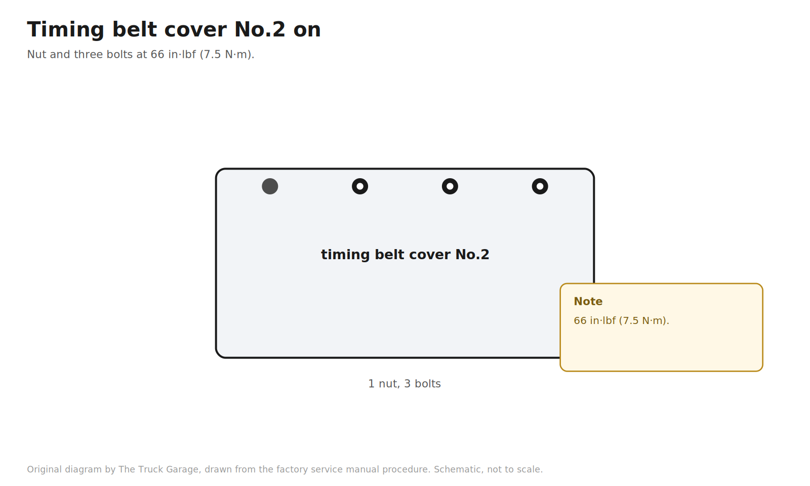
46. Install the timing belt cover No.2. Nut and three bolts, torqued to 66 in·lbf (7.5 N·m). [manual]
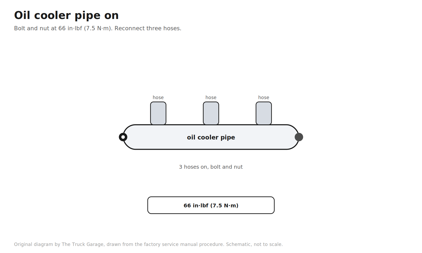
47. Install the oil cooler pipe. Bolt and nut, torqued to 66 in·lbf (7.5 N·m). Reconnect the three hoses. [manual]
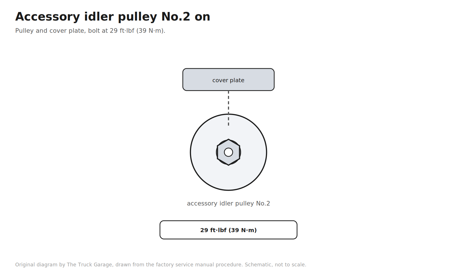
48. Install the accessory idler pulley No.2. Pulley and cover plate with the bolt, torqued to 29 ft·lbf (39 N·m). [manual]
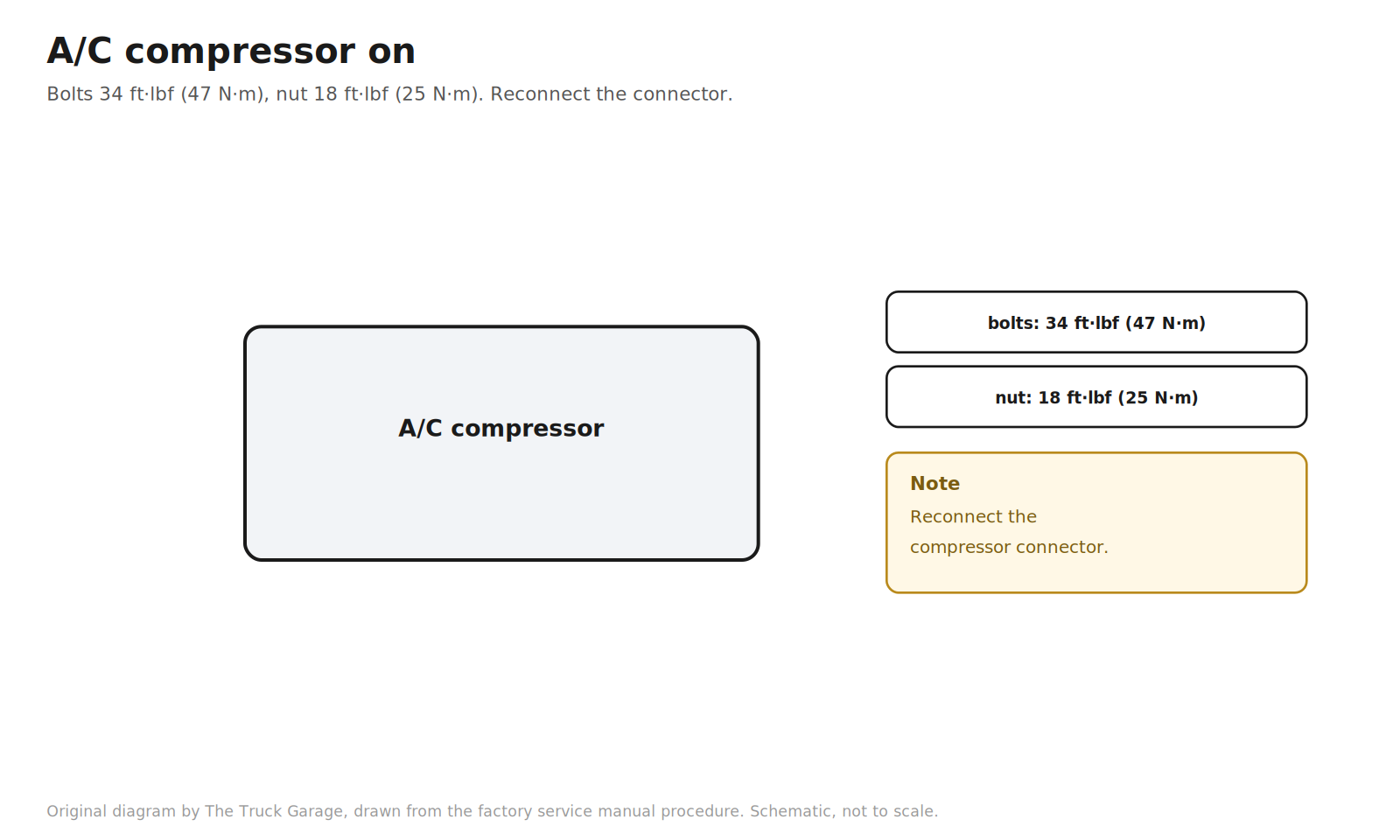
49. Install the A/C compressor. Stay, three bolts, and nut. Torque the bolts to 34 ft·lbf (47 N·m) and the nut to 18 ft·lbf (25 N·m). Reconnect the compressor connector. [manual]
50. Install the generator. [manual]
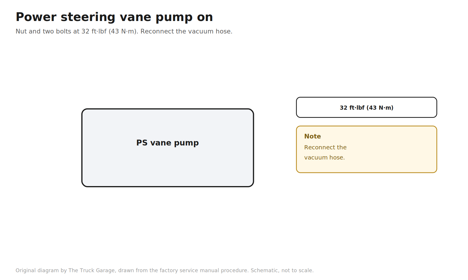
51. Install the power steering vane pump. Nut and two bolts, torqued to 32 ft·lbf (43 N·m). Reconnect the vacuum hose. [manual]
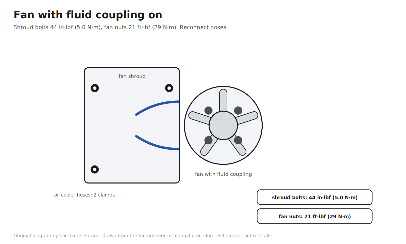
52. Install the fan with fluid coupling. Install the fan pulley. Lower the fan and shroud into the engine room together. Install the shroud with its three bolts, torqued to 44 in·lbf (5.0 N·m). Install the fan with its four nuts, torqued to 21 ft·lbf (29 N·m). Reconnect the two oil cooler hoses and their clamps. [manual]
53. Install the accessory V belt. Route the belt over every pulley except idler No.2. Turn the belt tensioner counterclockwise to slack it, then slip the belt onto idler No.2. After installing a new belt, check that the tensioner’s wear mark sits within the B range shown on the tensioner. [manual]
54. Reinstall the radiator support seal upper, the air cleaner hose, and the engine room covers. [manual]
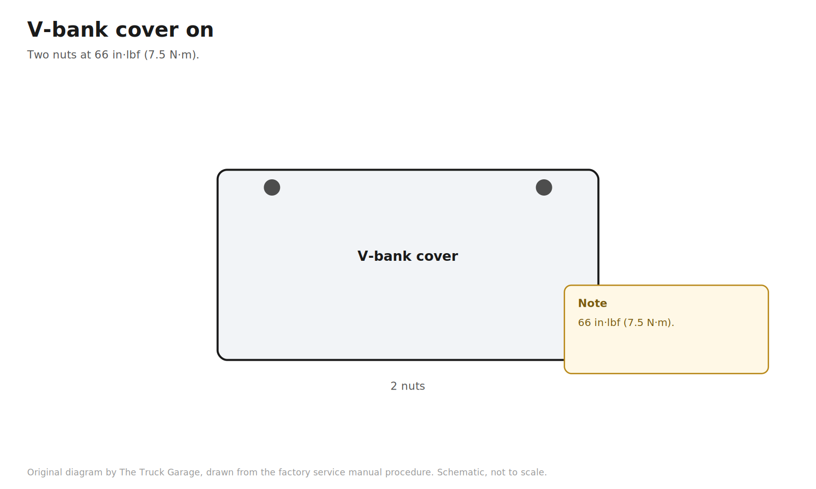
55. Install the V-bank cover. Two nuts, torqued to 66 in·lbf (7.5 N·m). [manual]
Verification and refill
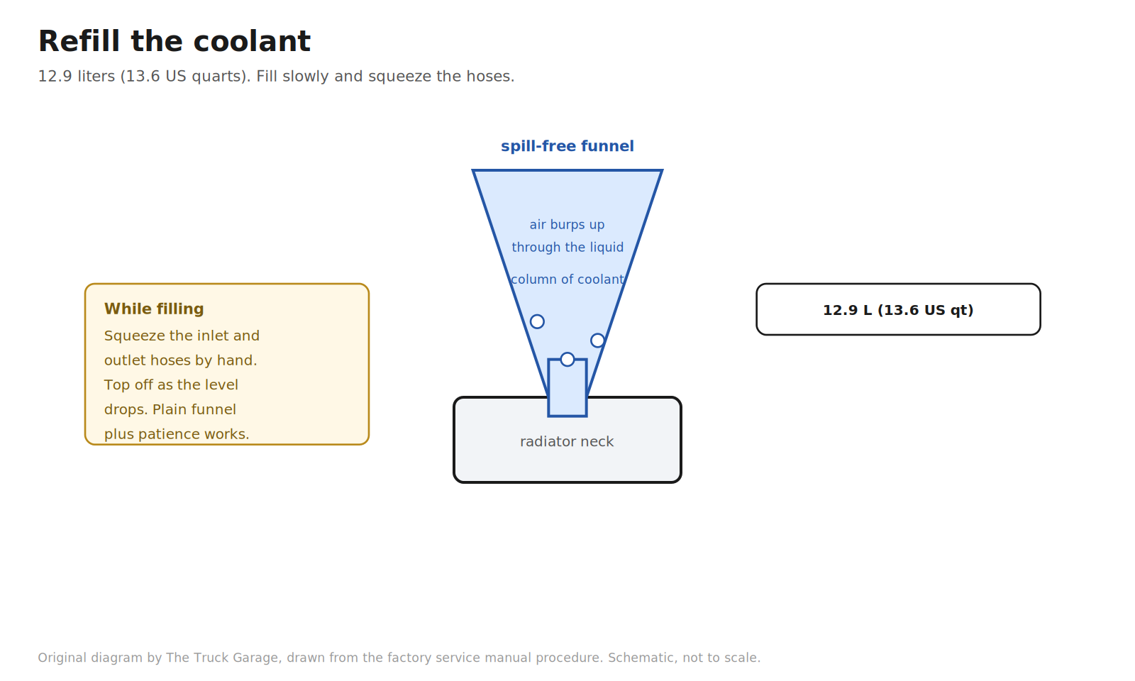
56. Refill the coolant. Slowly fill the cooling system. Capacity is 12.9 liters (13.6 US quarts). Use Toyota Super Long Life coolant or an equivalent high quality ethylene glycol coolant. Do not use plain water alone. Squeeze the inlet and outlet radiator hoses several times by hand while filling. If the coolant level drops, add more. This works air out of the system. Then install the radiator cap. [manual] Shadetree: a spill-free funnel sealed to the radiator neck holds a column of coolant above the system so trapped air burps out through liquid instead of spilling. A plain funnel and the hose-squeezing method above also work. [community]
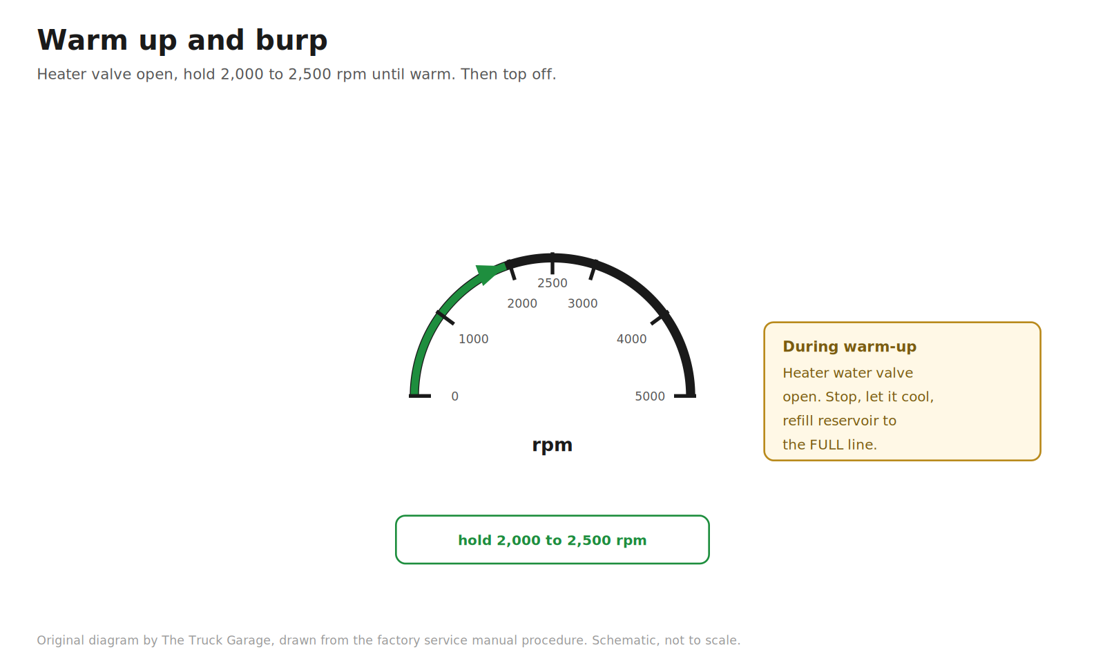
57. Warm up and burp. Start the engine and open the heater water valve. Hold the engine at 2,000 to 2,500 rpm until it warms up. Stop the engine and let the coolant cool down. Then refill the reservoir to the FULL line. [manual]
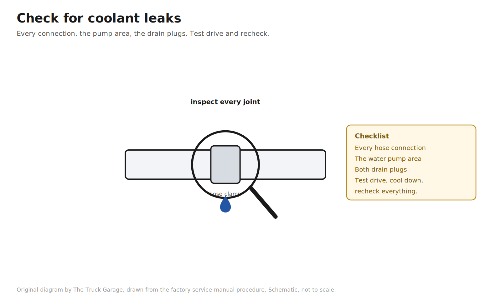
58. Check for coolant leaks. Inspect every hose connection, the water pump area, and the drain plugs. Take a short test drive, let it cool, and check the reservoir level and all connections once more. An air pocket left in the system can cause a sudden overheat, so do not skip the recheck. [community]
FAQ
Can I reuse the old timing belt if it looks fine?
The manual covers reusing a belt and says to check its installation marks, but you are replacing it. A new belt comes in the kit. A belt that looks fine at 90k miles is still a 90k-mile belt, and you have already done all the labor to reach it. [manual] [community]
Do I actually need the factory special tools?
Three matter. A crankshaft holding tool or one of the shadetree equivalents for the damper bolt. A puller for the damper, though loaner sets are free at parts stores and many dampers slide off by hand. And something to compress the tensioner, where a bench vise replaces the press. Everything else is standard sockets. [manual] [community]
What if the timing marks do not line up after the two revolutions?
The belt is a tooth off somewhere. Do not run the engine that way. Remove the belt and reinstall it. Recheck with another two clockwise revolutions until every mark aligns. [manual]
What happens if I accidentally turn the crankshaft with the belt off?
On the VVT-i 2UZ-FE, the pistons and valves share the same space at the wrong angles. If the crank or a cam gets turned with the belt off, stop. Reset everything per the procedure: cams to their marks, crank to its mark via the TDC procedure, then install the belt. Do not force anything that resists. [manual]
Why compress and pin the tensioner instead of just bolting it on?
The tensioner needs slack in the belt to seat properly. Compressing the push rod and pinning it holds the tensioner retracted while you bolt it down and route the belt. Pulling the pin afterward lets it extend against the belt with the correct tension. Bolting it on extended fights the belt and gives you the wrong tension. [manual]
Bottom line
That is the whole job, bolt by bolt, in the factory order. The procedure rewards patience and punishes shortcuts: set the crank before the belt comes off, keep every pulley clean, pin the tensioner before it goes on, torque every fastener to the book, and verify the marks with two clockwise revolutions before anything closes up. Do that and the 2UZ-FE gets its next 90,000 miles.
Sources
- 2005 Lexus GX470 factory repair manual. All torque specs and procedure steps.
- Lexus GX470 scheduled maintenance guide, timing belt interval of 90,000 miles or 108 months: https://carmanuals2.com/lexus/gx470-2005-scheduled-maintenance-guide-22229/page-29/
- Aisin TKT-021 application catalog: https://www.smythautoparts.com/catalog-2/itemdetail/aisin-world-corp-of-america/tkt-021
- Aisin TKT-001 (ships without hydraulic tensioner): https://www.smythautoparts.com/catalog-2/itemdetail/aisin-world-corp-of-america/tkt-001
- Counterfeit Aisin kit warning, owner reports: https://forum.ih8mud.com/threads/possible-fake-aisin-water-pumps-in-aisin-timing-belt-kits.1290877/page-2
- Crankshaft bolt removal methods, owner thread: https://forum.ih8mud.com/threads/crankshaft-bolt-removal.451642/
- Starter bump method discussion and breaker bar failures: https://forum.ih8mud.com/threads/is-this-right-to-loosen-the-cranshaft-pulley-with-starter-bump.354272/
- Parts store loaner tool programs: https://www.slashgear.com/1473130/everything-to-know-about-oreilly-loaner-tool-program/
- 2UZ-FE harmonic balancer puller discussion: https://forum.ih8mud.com/threads/2uz-fe-harmonic-balancer-puller-tool.960696/
- Spill-free funnel design and use: https://www.eppys.com/product/default-eppys/Spill-Free-Funnel/
- OEMTools no-spill funnel kit: https://www.autozone.com/p/oemtools-multi-purpose-funnel-87045/1340229
- Coolant funnel kit comparisons, owner discussion: https://bobistheoilguy.com/forums/threads/coolant-funnel-fill-kits-on-amazon-which-one.345479/
Leave a Reply