How one system makes two temperatures
The front air conditioning unit in the GX470, the GX460, and the GX550 cools air with one evaporator and warms air with one heater core. Every bit of air passes the evaporator first. After the evaporator, an air mix damper on each side decides how much of that cooled air goes through the heater core and how much goes around it. A small electric servo moves each damper, and the A/C amplifier drives each servo to the position the panel requests.
That layout produces the side-to-side split in two ways. A damper that stays partway toward the heater core warms its side while the other side cools normally. A low refrigerant charge reduces the cooling the evaporator can deliver, and owners report that the loss can show up on one side while the other side still feels cold. The two causes need different repairs, and each one can imitate the other at the vents. The diagnosis in this guide separates them with a thermometer, a servo sweep, a code check, and a pressure test, in that order.
The owner pattern needs evidence before it names a repair. Owners report that a low charge often warms the passenger side first on dual-zone Lexus trucks, and one Lexus Owners Club thread records a passenger side split that a shop traced to a low charge after the servos tested good. Treat the pattern as a reason to run the gauge test in Step 4. A side order alone never proves the charge is low.
Scope for GX550 owners. The GX550 runs the same dual-zone layout on a different refrigerant, HFO-1234yf (R1234yf), and its charge amounts, gauge readings, and servo codes print in the steps below beside the GX470 and GX460 values. Two steps change on a GX550. The truck has no sight glass, so its refrigerant check starts at the gauge test in Step 4, and its servo tests and codes run through a scan tool at the DLC3 connector.
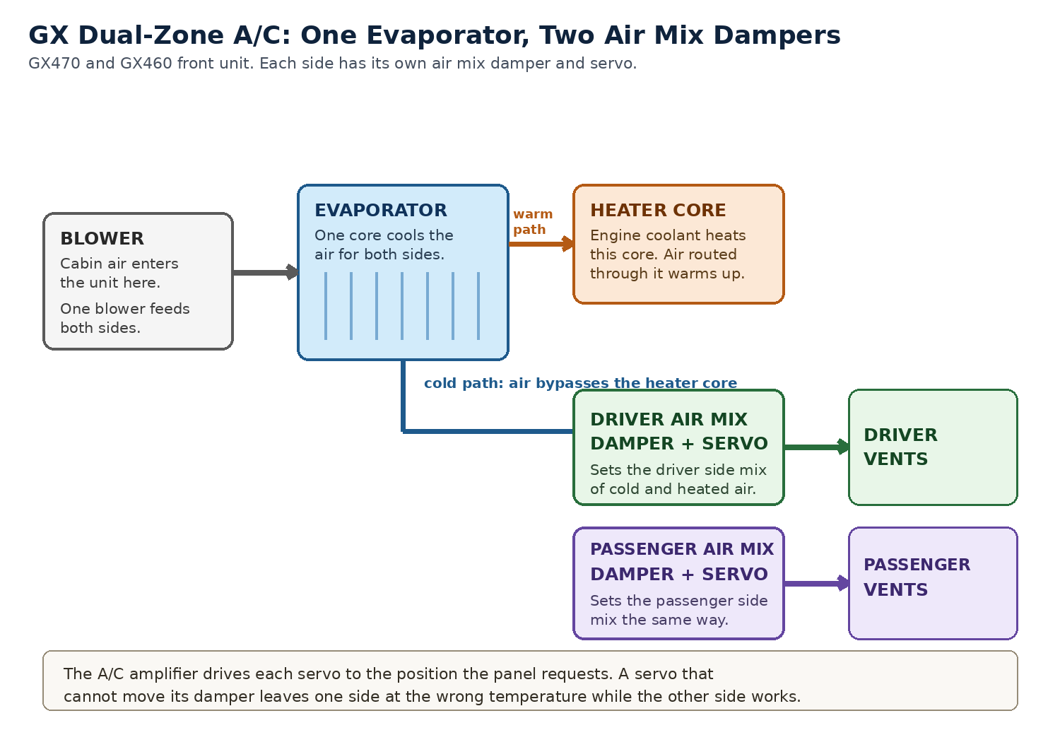
Dual-zone layout. One evaporator cools both sides, and one air mix damper and servo per side set each side temperature.
Parts and tools
Gather the thermometer and the code reading method before the diagnosis steps. The parts list grows only after a check names a failed part.
| Item | Used for |
|---|---|
| Probe thermometer, or a thermometer with a second wired probe | The vent temperature measurement in Step 1 and the sweep readings in Step 2 |
| Flashlight and inspection mirror | Watching servo arms move during the sweep test where access allows |
| Trim removal tools for the glove box and lower trim | Access to watch the passenger side servos on a GX470 |
| Scan tool that reads body and A/C codes | The GX460 and GX550 code checks in Step 3. A GX470 uses its panel sensor check for the first code read |
| Manifold gauge set for R134a | The shop-level pressure test in Step 4 on R134a trucks. Trucks on HFO-1234yf take a gauge set built for that refrigerant, with different couplers |
| Electronic leak detector and a UV light for dye work | The leak check in Step 4, before any recharge |
| Safety glasses and nitrile gloves | Refrigerant work in Step 4 and the handling rules at the end of this guide |
| Inch-pound torque wrench, 20 to 200 in·lbf | Refrigerant line fasteners in the Step 5 tables, if a line was opened |
| Cabin air filter, GX470 or GX460 | The airflow check before the diagnosis. A clogged filter cuts airflow to both sides and can exaggerate a small split |
Replacement parts to have only when a check calls for them: the air mix damper servo for the side that failed the sweep, from the table in Step 5, and refrigerant line O-rings for any joint opened during related work. Refrigerant itself belongs to the shop step in Step 4, because the charge goes in by measured weight after a leak check.
Step 1: Measure both vent temperatures
Start with numbers. A hand at the vent can feel a split, and a thermometer records how large the split is and whether it repeats.
- Warm the engine fully and park out of direct sun where possible.
- Turn the dual-zone control to a single setting for both sides. On trucks with a sync function, turn sync on. Set the shared temperature to the coldest setting.
- Turn the A/C on, set the air inlet to recirculation, and set the blower to a high setting.
- Place one thermometer probe in the driver center vent and one in the passenger center vent. A single thermometer works when you move it between vents after each side stabilizes, and two probes give a cleaner comparison.
- Run the system for several minutes, then record both vent readings, the temperature setting, the blower setting, and the outside temperature.
A repeatable split under identical settings is the finding. Record the size of the split in degrees, because the retest at the end of the diagnosis uses the same setup and the same two vents. This guide prints no target vent temperature. The comparison between the two sides under one setting carries the test. The general code reading background in the Truck Garage dash warning lights guide applies to the scan tool work later in this diagnosis: Dash Warning Lights Guide.
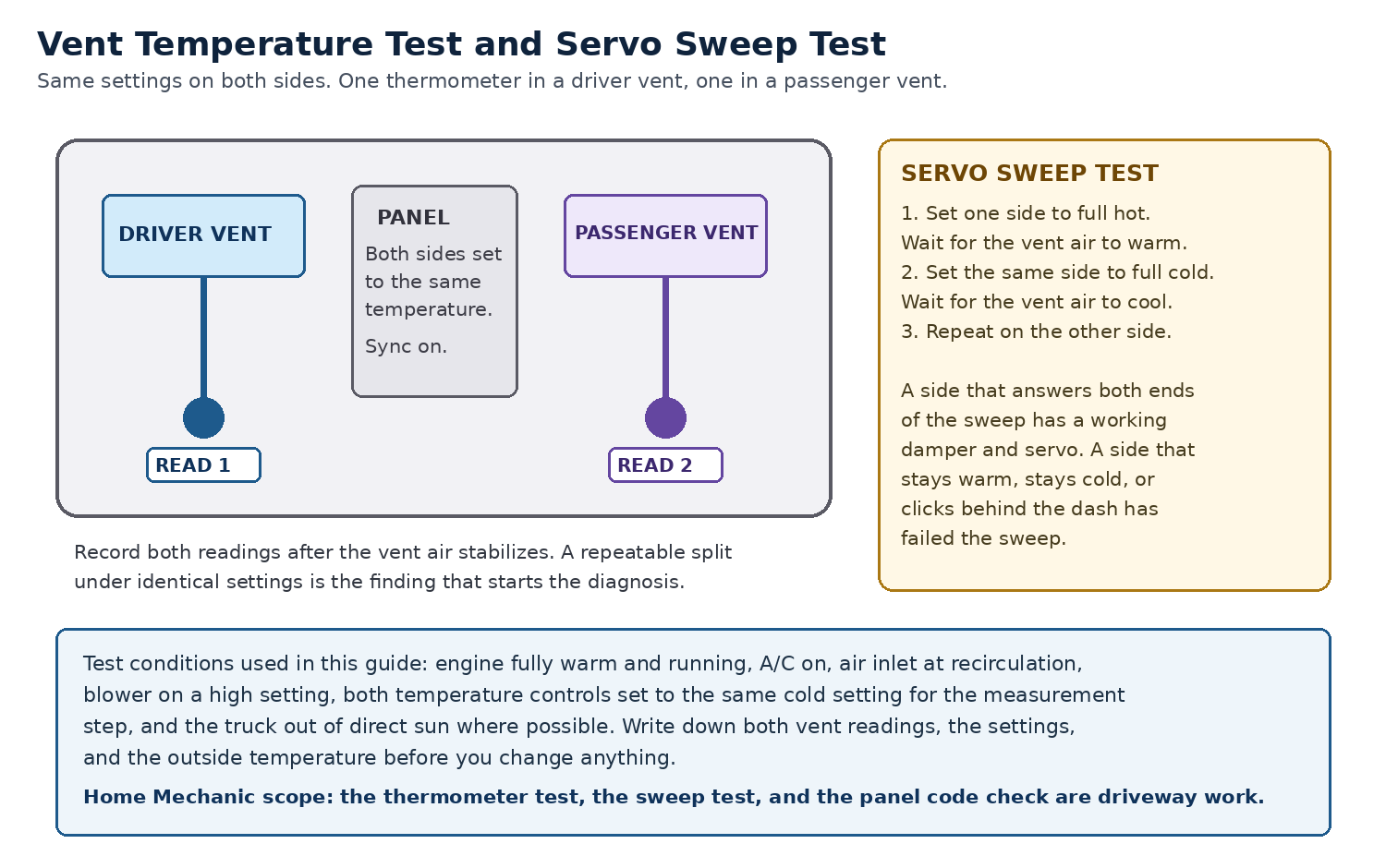
Vent temperature test and servo sweep test. Same settings on both sides, one thermometer per side.
Step 2: Sweep each servo from full hot to full cold
The sweep test proves whether each air mix damper moves through its full travel. Run it one side at a time, with the other side left at a fixed setting.
- Keep the engine running with the A/C on and the blower at a medium or high setting.
- Set the driver side to full hot. Wait for the driver vent air to warm fully, then set the driver side to full cold and wait for the vent air to cool.
- Repeat the same full hot to full cold sweep on the passenger side.
- Listen at the dash during each sweep. A healthy servo moves quietly. Clicking, repeated hunting, or a servo sound that stops while the vent temperature stays fixed all mark a failed sweep on that side.
- Watch the servo arms where access allows. On a GX470, owners in the ClubLexus thread in the Sources section describe removing the glove box and watching the servo arms move as the temperature setting changes, and they name the arm that clicks or does not move as the faulty one. The IH8MUD servo thread in the Sources section records a GX470 owner dismounting a servo and watching it struggle to move its arm while the damper itself moved freely by hand.
Read the sweep results by side. A side that warms fully at full hot and cools fully at full cold has passed the sweep. Its damper and servo move through the full range. A side that stays warm at full cold has failed the sweep. Its damper is stuck toward the heater core, its servo is not moving the damper, or its linkage is disconnected. A side that stays cold at full hot has also failed the sweep. Its damper is stuck away from the heater core. A failed sweep sends the diagnosis to the servo branch in Step 3 and Step 5, and the refrigerant branch waits until both sides pass.
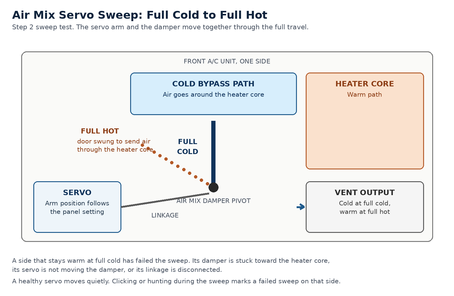
Servo sweep. The servo arm and the damper move together from full cold to full hot.
The GX550 sweep runs from a scan tool. The GX550 service order for this complaint starts with a scan tool refrigerant gas volume check, then runs Active Tests that drive the front left, front right, and rear air mix damper servos while you watch the vent temperatures change. A side that does not follow the Active Test command has failed the sweep the same way, and the codes in Step 3 name the circuit.
A heat mode split with both sweeps passing has one more owner reported suspect. Owners in the ClubLexus thread raised a partly clogged heater core as a theory on a GX470 that heated on the driver side and stayed cold on the passenger side with its servos moving. That point is owner experience on a heating complaint, and this guide claims no factory finding for it. Work the A/C cooling diagnosis in this guide first, and treat a heat-only split as a coolant flow check after the servos pass.
Step 3: Read the codes
Codes support the sweep result. Run the code check after the sweep, and record every code before clearing anything.
GX470 panel sensor check. The GX470 reads its A/C codes on the panel itself, with no scan tool required for the first pass.
- Hold the AUTO switch and the R/F (recirculation and fresh) switch down together, and turn the ignition switch ON while holding them.
- Watch the indicator check. The indicators come on and go off four times in succession at one second intervals.
- Read the codes on the temperature display after the indicator check completes. The display shows each code in turn. Step the display with the UPDr switch on 2003 to 2006 trucks and with the FRONT DEF switch on 2007 to 2009 trucks when a slower read is needed.
- Run the actuator check from the same mode when the sweep result needs confirmation. Press the R/F switch after entering the sensor check, and the dampers, motors, and relays cycle at one second intervals while you check the temperature and the airflow by hand at the vents.
- Clear the codes only after recording them. Press the FRONT DEF switch and the REAR DEF switch at the same time during the sensor check, or pull the ECU-B fuse in the engine room junction block for 20 seconds or longer.
| GX470 code | Circuit | Side |
|---|---|---|
| 31 | Air mix damper position sensor circuit | Passenger side |
| 36 | Air mix damper position sensor circuit | Driver side |
| 41 | Air mix damper control servomotor | Passenger side |
| 46 | Air mix damper control servomotor | Driver side |
| 32 | Air inlet damper position sensor circuit | No side; plays no part in a temperature split |
The air mix damper position sensor is built into the air mix damper servo sub-assembly on this system. Code 32 belongs to a different circuit, the air inlet damper position sensor. A solar sensor code can appear during a garage check, and owners in the IH8MUD thread treat code 21 as normal in a garage or carport out of direct sun.
GX460 scan tool codes. The GX460 reads its A/C codes with a scan tool that covers body systems.
| GX460 code | Circuit | Side |
|---|---|---|
| B1441 | Air mix damper control servo motor circuit | Passenger side |
| B1446 | Air mix damper control servo motor circuit | Driver side |
| B1442 | Air inlet damper control servo motor circuit | No side |
| B1443 | Air outlet damper control servo motor circuit | No side |
| B1447 | Rear air mix damper control servo motor circuit | Rear |
The GX460 servo names in the parts and data lists match that split: the No. 1 air conditioning radiator damper servo sub-assembly is the driver side air mix damper servo, and the No. 2 unit is the front passenger side air mix damper servo. A rear split complaint on a GX460 uses the rear air mix code, B1447, and it follows the same sweep first order at the rear vents.
GX550 scan tool codes. The GX550 reads its A/C codes with a scan tool at the DLC3 connector, and it has no panel check. Left is the driver side on a left-hand-drive truck, and right is the passenger side. The front left servo is the No. 2 air mix damper servo sub-assembly, and the front right servo is the air mix damper servo sub-assembly without a number.
| GX550 code | Servo | Meaning |
|---|---|---|
| B144B-87 | Front left air mix damper control servo | Lost communication with the servo on the LIN bus |
| B144C-7F | Front left air mix damper control servo | Actuator stuck off |
| B145A-87 | Front right air mix damper control servo | Lost communication with the servo on the LIN bus |
| B145B-7F | Front right air mix damper control servo | Actuator stuck off |
| B140B-87 | Rear air mix damper control servo | Lost communication with the servo on the LIN bus |
| B140C-7F | Rear air mix damper control servo | Actuator stuck off |
Read every code as a circuit name. A code names the servo circuit for one side, and that circuit includes the servo, the harness and connectors between the servo and the A/C amplifier, and the amplifier itself. On the GX550, a lost communication code names the LIN communication line between the amplifier and that servo. A code paired with a failed sweep on the same side supports a servo repair on that side, after the connector and harness check in Step 5. A code with a passing sweep points at the position sensing side of the circuit and at intermittent faults, and it calls for the circuit checks before any part order. No code with a failed sweep still leaves the servo branch in charge, because the sweep tested the damper movement directly. No code with two passing sweeps sends the diagnosis to the refrigerant branch in Step 4. The RX300 owner thread in the Sources section records that exact case: no error code, servos confirmed working, and a low charge at the shop.
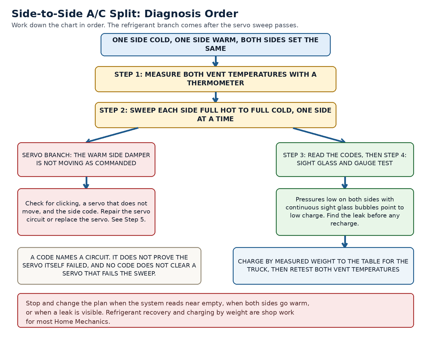
Diagnosis order. The refrigerant branch comes after both sides pass the servo sweep.
Step 4: Test the refrigerant, only after the sweep passes
Open this branch when both sides pass the sweep, or when both sides lose cooling together. Refrigerant work has a hard scope line for the Home Mechanic. The sight glass check and the gauge reading are observations. Recovery, evacuation, leak repair, and charging by weight take recovery equipment and a scale, and most Home Mechanics hand those steps to a shop with the diagnosis notes from Steps 1 to 3 attached.
Check the sight glass where the truck has one.
| Truck | Sight glass | Refrigerant check starts at |
|---|---|---|
| GX470, 2003 to 2009 | Yes, every year | Sight glass check below, then the gauge test |
| GX460, built before August 2020 | Yes | Sight glass check below, then the gauge test |
| GX460, built from August 2020 | No | The gauge test below |
| GX550 | No | The gauge test below |
Run the sight glass test under the same conditions on both models: engine at 1,500 rpm, blower on HI, A/C on, temperature control at MAX COOL, and doors fully open.
| What the glass shows | What it means | Next step |
|---|---|---|
| Bubbles visible during the test | Insufficient refrigerant | Leak check and repair first, then add refrigerant until the bubbles disappear |
| Clear glass | The system can be empty, insufficient, correct, or overcharged | The gauge test below separates those four cases |
| Bubbles with higher than usual ambient temperature | Can be acceptable | Accept it when cooling is sufficient at the vents |
| Continuous bubbles, GX470 2003 to 2006, with low pressure on both gauges | The insufficient refrigerant pattern for those years | Leak check and repair, then a weighed charge (Step 4) |
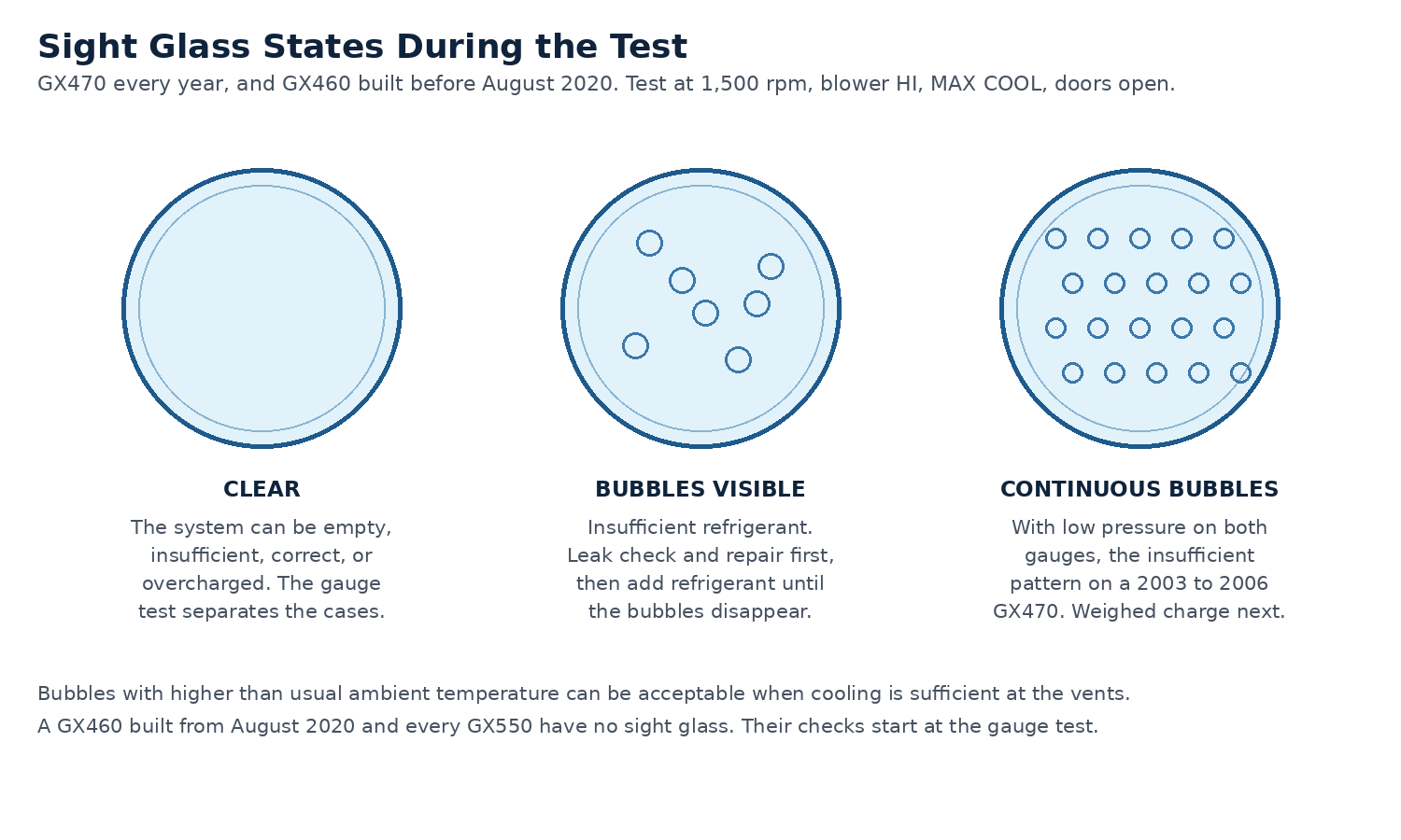
Sight glass states. A clear glass, bubbles visible, and continuous bubbles during the test.
Run the manifold gauge test under the conditions for your truck.
- GX470, 2003 to 2006: air inlet at recirculation with inlet air at 30 to 35 °C (86 to 95 °F), engine at 1,500 rpm, blower on HI, temperature control at COOL, A/C on, doors fully open.
- GX470, 2007 to 2009: inlet air at 30 to 35 °C (86 to 95 °F), engine at 1,500 rpm, blower on HI, temperature control at MAX COOL, A/C on, doors fully open.
- GX460, built before August 2020: inlet air at 30 to 35 °C (86 to 95 °F), engine at 1,500 rpm, blower on HI, A/C on, doors fully open.
- GX460, built from August 2020: the same conditions with the temperature control at max cold.
- GX550: doors fully open, ignition switch on, A/C switch on, temperature at max cool, blower on high, inlet air at recirculation at 30 to 35 °C (86 to 95 °F). The GX550 conditions state no engine speed.
| Truck | Low side, normal | High side, normal |
|---|---|---|
| GX470, 2003 to 2009 | 150 to 250 kPa (22 to 36 psi) | 1,370 to 1,570 kPa (199 to 228 psi) |
| GX460, 2010 to 2013 | 150 to 250 kPa (22 to 36 psi) | 1,370 to 1,570 kPa (199 to 228 psi) |
| GX460, 2014 to 2023 | 147 to 245 kPa (21 to 36 psi) | 1,373 to 1,569 kPa (199 to 228 psi) |
| GX550 | 150 to 250 kPa (22 to 36 psi) | 1,370 to 1,570 kPa (199 to 228 psi) |
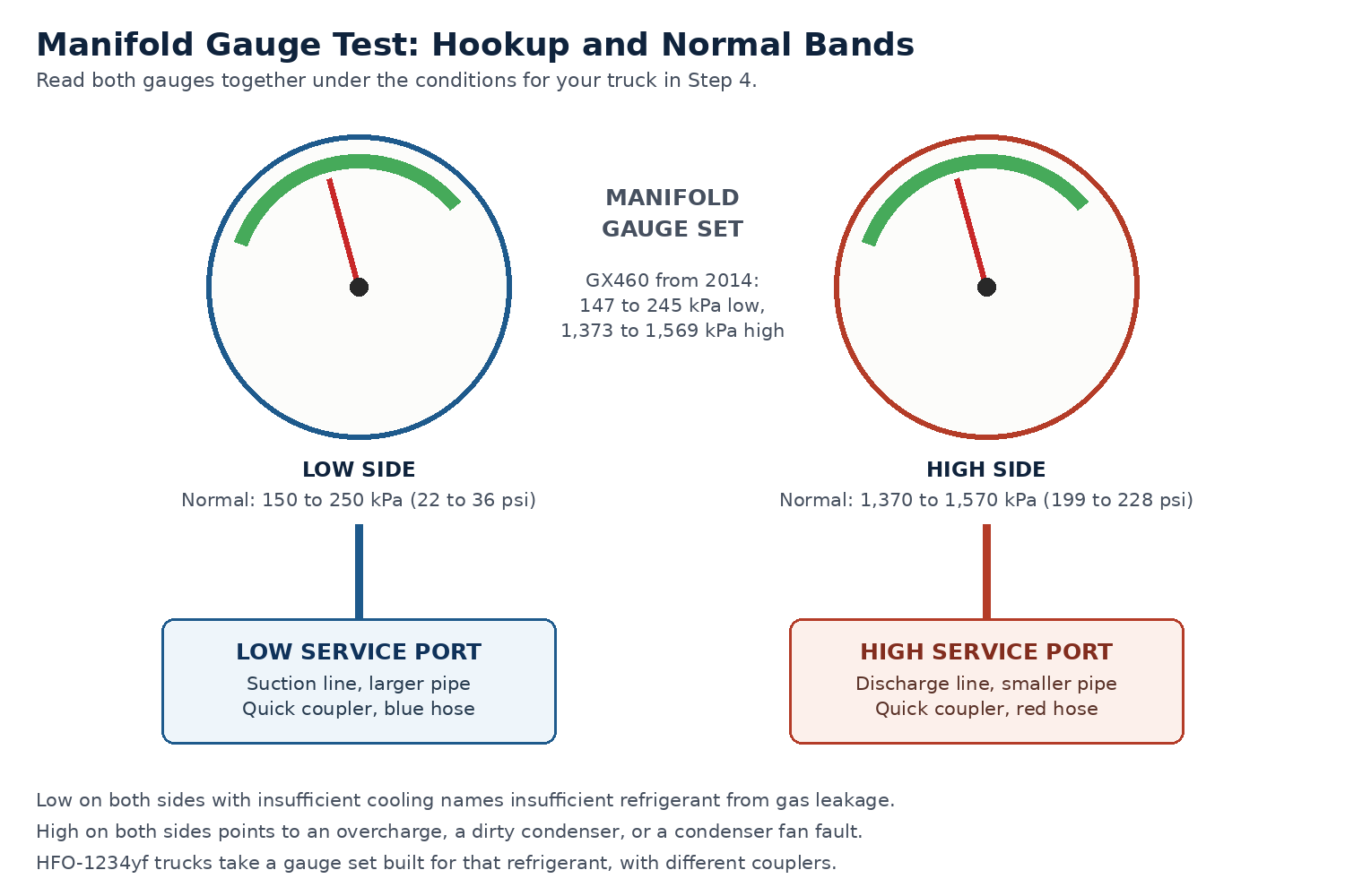
Gauge hookup. The low side hose goes to the suction line port, and the high side hose goes to the discharge line port.
Read the insufficient pattern as a pair. On all three models, pressure low on the low side and the high side together, with insufficient cooling, names insufficient refrigerant from gas leakage as the probable cause. On a GX470 from 2003 to 2006, the pattern adds bubbles seen through the sight glass continuously. The listed response runs in a fixed order: check for gas leakage and repair the leak, then supply the proper amount of new refrigerant, and evacuate the system first when the pressure reads close to 0 at the gauge connection. Pressure high on both sides points away from a low charge, toward an overcharge, a dirty condenser, or a condenser fan fault, and the condenser face and fan deserve a look before any refrigerant decision. The condenser shares the front stack with the radiator, and the Truck Garage radiator guide shows that stack during a radiator replacement: GX470 Radiator Preventative Replacement.
Find the leak before any recharge. A system that lost charge has a leak path, and common leak points include the service valves, the hose crimps, the condenser, and the line O-rings. The RX300 owner thread records a shop that vacuum tested the system, replaced two valves, and refilled with fluorescent dye after the first check found no leak location. Dye and an electronic detector give the next low charge event a visible starting point. A recharge with no leak check gives a temporary result, and the split returns as the charge falls again.
Charge by measured weight. The proper charge is a weighed amount for the configuration of the truck, measured into an evacuated system. Topping off by can pressure alone cannot confirm the amount in the system, and it skips the leak check and the evacuation. The GX460 refrigerant changed during the production run, at August 2020, and the table carries both refrigerants.
| Truck and configuration | Refrigerant | Charge amount |
|---|---|---|
| GX470 single A/C, 2003 to 2006 | HFC-134a (R134a) | 650 ±30 g (22.92 ±1.06 oz) |
| GX470 single A/C, 2007 to 2009 | HFC-134a (R134a) | 600 ±30 g (21.16 ±1.06 oz) |
| GX470 dual A/C, 2003 to 2006 | HFC-134a (R134a) | 800 ±30 g (28.21 ±1.06 oz) |
| GX470 dual A/C, 2007 to 2009 | HFC-134a (R134a) | 720 ±30 g (25.39 ±1.06 oz) |
| GX460 without rear cooler, built before August 2020 | HFC-134a (R134a) | 550 ±30 g (19.3 ±1.1 oz) |
| GX460 with rear cooler and without cool box, built before August 2020 | HFC-134a (R134a) | 810 ±30 g (28.6 ±1.1 oz) |
| GX460 with rear cooler and with cool box, built before August 2020 | HFC-134a (R134a) | 860 ±30 g (30.3 ±1.1 oz) |
| GX460 without rear cooler, built from August 2020 | HFO-1234yf (R1234yf) | 520 to 580 g |
| GX460 with rear cooler and without cool box, built from August 2020 | HFO-1234yf (R1234yf) | 770 to 830 g |
| GX460 with rear cooler and with cool box, built from August 2020 | HFO-1234yf (R1234yf) | 840 to 900 g |
| GX550 without rear A/C and without cool box | HFO-1234yf (R1234yf) | 590 to 650 g (20.9 to 22.9 oz) |
| GX550 without rear A/C and with cool box | HFO-1234yf (R1234yf) | 640 to 700 g (22.6 to 24.6 oz) |
| GX550 with rear A/C and without cool box | HFO-1234yf (R1234yf) | 770 to 830 g (27.2 to 29.2 oz) |
| GX550 with rear A/C and with cool box | HFO-1234yf (R1234yf) | 820 to 880 g (29.0 to 31.0 oz) |
The GX460 procedure for trucks built before August 2020 adds two points that apply to any weighed charge on those trucks. About 100 g (3.53 oz) of refrigerant may still be needed after the sight glass bubbles disappear, and the amount is checked by measuring the quantity, with the sight glass used as a guide only. After a recharge, the leak check runs with the engine stopped and some refrigerant in the system: with the compressor off, about 392 to 588 kPa (57 to 85 psi) should remain in the system during that check. The same compressor-off leak check pressure applies to the GX550.
Retest after the charge with the Step 1 setup. Record both vent readings under the same settings, and compare the split against the Step 1 record. A split that survives a correct weighed charge with both sweeps passing sends the diagnosis back to the servo circuit checks in Step 3, with the harness and amplifier side of the circuit next in line.
Step 5: Replace the servo when the checks name it
Servo replacement in this guide stays at overview depth. Access varies by side and by model, and the full removal order belongs to the factory procedure for the specific truck.
Confirm the part before removal. The failed side comes from the sweep in Step 2 and the code in Step 3, and the two results should agree on the side. Check the servo connector for pushed out terminals, corrosion, and a harness that pulls tight at full damper travel before ordering the part. Move the damper by hand where access allows, the way the IH8MUD owner did, and confirm the damper itself travels freely. A damper that binds in the unit housing makes a new servo fail the same way.
| Air mix damper servo | GX470 | GX460 |
|---|---|---|
| Passenger side | 87106-35180 | No. 2 servo, 87106-60230 |
| Driver side | 87106-35150 | No. 1 servo, 87106-60220 |
The GX470 passenger servo number changes at a supersession. Trucks built before February 2004 carry 87106-35140, and 87106-35180 supersedes it. Order the GX470 driver side servo by its number, 87106-35150, and match it against the failed unit on the bench before installation. The two GX460 numbers run the full 2010 to 2023 range with no change.
Access on the GX470. Owners in the ClubLexus thread describe the passenger side servos as reachable after glove box removal, with the servo arms visible as the temperature setting changes. The IH8MUD thread records a driver footwell servo reached after popping the trim beside the gas pedal, held by three screws. Other servo positions on the unit need more trim and dash work, and a servo mounted deep behind the dash belongs at a shop for a first time repair.
Access on the GX460. The driver side air mix servo is the No. 1 air conditioning radiator damper servo sub-assembly, and the front passenger side air mix servo is the No. 2 unit. Order by side and model year from the table above.
Initialize after replacement where the procedure requires it. On a GX460 from 2013 onward, run the servo motor initialization through the air conditioning system utility with a scan tool after damper servo replacement. Skipping initialization leaves the amplifier without a learned damper position, and the new servo can set the same code again. On 2010 to 2012 GX460 trucks, confirm the repair with the Step 2 sweep and a code recheck. On a GX550, run Servomotor Initialization from the scan tool utility at Body Electrical, Air Conditioner, Utility after any air mix servo replacement; skipping it leaves the truck setting DTCs. On a GX470, run the actuator check from Step 3 after replacement and confirm that the new servo cycles with the rest of the dampers, then repeat the Step 2 sweep on the repaired side.
The GX550 servo job sits at shop depth. The GX550 servos come off only with the air conditioning unit apart, after refrigerant recovery, a coolant drain, and instrument panel removal. That depth puts a GX550 servo replacement at a shop for most Home Mechanics, and the torque tables below cover the refrigerant lines that the job opens on the way in.
Use the torque tables only for the refrigerant lines a related job opened. The tables below cover the compressor and condenser line fasteners that a condenser or compressor job touches, and they apply only when those joints were opened.
GX470 refrigerant line torque values
| Connection | Torque |
|---|---|
| Discharge hose x compressor | 87 in·lbf (9.8 N·m) |
| Suction hose x compressor | 87 in·lbf (9.8 N·m) |
| Compressor and magnetic clutch x engine, bolt | 34 ft·lbf (46 N·m) |
| Compressor and magnetic clutch x engine, nut | 18 ft·lbf (24 N·m) |
| Air conditioning tube assembly x cooler evaporator sub-assembly No. 1 | 30 in·lbf (3.5 N·m) |
GX460 refrigerant line torque values
| Connection | Torque |
|---|---|
| No. 1 cooler refrigerant discharge hose x cooler condenser assembly | 48 in·lbf (5.4 N·m) |
| Air conditioning tube assembly x cooler condenser assembly | 48 in·lbf (5.4 N·m) |
| Suction hose x cooler compressor assembly | 87 in·lbf (9.8 N·m) |
| Discharge hose x cooler compressor assembly | 87 in·lbf (9.8 N·m) |
GX550 refrigerant line torque values
| Connection | Torque |
|---|---|
| No. 1 cooler refrigerant discharge hose x compressor | 87 in·lbf (9.8 N·m) |
| Suction hose sub-assembly x compressor | 87 in·lbf (9.8 N·m) |
| No. 2 air conditioning tube and accessory assembly x cooler condenser assembly, Bolt A | 87 in·lbf (9.8 N·m) |
| No. 2 air conditioning tube and accessory assembly x cooler condenser assembly, Bolt B | 48 in·lbf (5.4 N·m) |
| Cooler condenser assembly x radiator assembly, bolt | 87 in·lbf (9.8 N·m) |
| Cooler condenser assembly x radiator assembly, nut | 87 in·lbf (9.8 N·m) |
| Air conditioning tube and assembly x No. 1 cooler evaporator sub-assembly | 31 in·lbf (3.5 N·m) |
Send the job to a shop when the evidence lands there. A servo buried behind the full dash, a harness fault that needs circuit testing at the amplifier, a failed amplifier, and every refrigerant recovery and weighed charge step belong at a shop for most Home Mechanics. Take the Step 1 readings, the sweep results, and the recorded codes with the truck. Those three records keep the shop diagnosis on the branch the evidence already chose.
Stop conditions and refrigerant handling
Stop the diagnosis and change the plan when any of these shows up.
Pressure close to 0 at the gauge connection. The system is empty or nearly empty. The factory response is leak inspection and repair, then evacuation, then a weighed charge. Running the compressor on an empty system damages it, and the GX460 charge procedure warns against operating the compressor before charging because it overheats without refrigerant.
A visible leak or an oily line joint. Oil at a fitting, a hose crimp, or the condenser marks the leak path that refrigerant is leaving through. Repair the leak point before any charge work, and replace the O-rings at every joint that opens.
Both sides warm together with a blinking A/C indicator or a compressor that never engages. The complaint has left the side-to-side split diagnosis. Compressor lock, pressure switch, and amplifier faults live on that branch, and the code check in Step 3 is the entry point.
Refrigerant handling rules for every step in this branch. Refrigerant is recovered with recovery equipment, and venting refrigerant to the air is prohibited. Wear eye and skin protection during any line or service port work, because liquid refrigerant causes frostbite burns on contact. Keep hands, tools, and loose clothing clear of the belt, the fan, and the compressor clutch while the engine runs for the gauge test. A Home Mechanic without recovery equipment stops after the sight glass and gauge observations and hands the truck to a shop for the sealed system work.
FAQ
Is low refrigerant the cause when the driver side blows cold and the passenger side blows warm?
Low refrigerant is one of the two main causes, and a failed passenger side air mix servo is the other. Owners report that a low charge can warm one side while the other side still cools. The servo sweep in Step 2 separates the two causes in minutes: a passenger side that fails the sweep has a servo branch fault, and a passenger side that passes the sweep sends the diagnosis to the gauge test in Step 4 for the charge answer.
Can I add a can of refrigerant and see whether the split goes away?
A can added with no leak check gives a temporary result at best. The system lost the charge through a leak, the split returns as the charge falls, and can pressure cannot confirm the weighed amount the system holds. The factory order is leak check and repair first, then evacuation, then a charge measured by weight to the table for the truck configuration in Step 4.
What does clicking behind the dash mean during a temperature change?
Owners in the ClubLexus and IH8MUD threads in the Sources section tie clicking to a servo that cannot move its damper cleanly. Clicking that arrives with a failed sweep on the same side supports the servo branch. Record the side, run the code check in Step 3, and check the connector and the damper travel by hand before ordering the servo.
What do GX470 codes 31 and 36 mean?
Code 31 names the air mix damper position sensor circuit on the passenger side, and code 36 names the same circuit on the driver side. The control servomotor codes pair the same way, with code 41 for the passenger side and code 46 for the driver side. The position sensor is built into the air mix damper servo sub-assembly, so a confirmed sensor circuit fault on a side that also failed its sweep usually ends at that side servo, after the harness and connector check. The code names a circuit, and the circuit checks come before the part order.
What do GX460 codes B1441 and B1446 mean?
Code B1441 names the air mix damper control servo motor circuit on the passenger side, and code B1446 names the same circuit on the driver side. The passenger servo is the No. 2 air conditioning radiator damper servo sub-assembly, and the driver servo is the No. 1 unit. A replacement GX460 servo on a 2013 or later truck needs the servo motor initialization step after installation.
Which refrigerant does my GX460 use?
GX460 trucks built before August 2020 use HFC-134a (R134a). Trucks built from August 2020 use HFO-1234yf (R1234yf), and the sight glass disappears at the same changeover. The two refrigerants take different service couplers, and the charge amounts differ by refrigerant, so read the truck’s build date before connecting a gauge set. Step 4 carries the charge table for both refrigerants.
Why would one side warm up first on a low charge?
Owners report the pattern, and the Lexus Owners Club RX300 thread records a passenger side split that cleared after a shop found the charge low and refilled by weight. This guide treats the pattern as owner experience only. The gauge readings and the weighed charge in Step 4 provide the evidence that settles a low charge call on a GX.
Can I keep driving with a side-to-side split?
Driving with a split from a failed servo harms comfort only, and the repair can wait for parts. Driving on a low charge is a different case. A charge that keeps falling can reach the point where the compressor runs with too little refrigerant, and the stop conditions section covers the empty system risk. Get the gauge test done promptly when the sweep passes on both sides.
Does this diagnosis apply to the GX550?
Yes, with the GX550 values that print in the steps. Set both sides the same, measure both vents, and sweep each side the same way. The GX550 sweep and code check run through a scan tool, the truck has no sight glass, and its refrigerant is HFO-1234yf (R1234yf) with the charge amounts in the Step 4 table. A GX550 servo replacement sits at shop depth, because the servos come off only with the air conditioning unit apart.
Sources
- GX470 factory manuals: Heater and Air Conditioner sections (refrigerant on-vehicle inspection, manifold gauge test, refrigerant replacement, service data, torque specifications) and Diagnostics, Air Conditioning System (diagnosis check mode, DTC chart, actuator check, air mix damper position sensor)
- GX460 factory manuals: Heating and Air Conditioning sections (DTC list, refrigerant on-vehicle inspection, refrigerant replacement, service data, torque specifications) and Introduction and Air Conditioning data list sections (replacement procedures, damper servo naming, servo motor initialization)
- GX550 repair manuals: Air Conditioning sections (refrigerant service data and replacement, on-vehicle inspection, DTC chart, data list, necessary procedures, torque specifications)
- ClubLexus, Driver side heat, passenger side cold air, https://www.clublexus.com/forums/gx-1st-gen-2003-2009/666583-driver-side-heat-passenger-side-cold-air.html
- IH8MUD, 04 GX470 Heat/ac servos help, https://forum.ih8mud.com/threads/04-gx470-heat-ac-servos-help.1304062/
- Lexus Owners Club, No cold air from passenger side vents (RX300), https://us.lexusownersclub.com/forums/topic/91859-no-cold-air-from-passenger-side-vents/
- Lexus Parts, parts diagrams and part lookup by VIN, https://parts.lexus.com/
Leave a Reply