Quick answer
The conversion replaces the navigation center stack in a 2003 to 2009 GX470 with the climate control panel, matching control unit, brackets, and bezel from a GX470 that was built without navigation. Owners report that the swap moves climate control off the factory touchscreen and onto a separate physical panel with its own display. Owners also report that the freed opening then accepts a standard aftermarket head unit in place of the integrated factory display arrangement.
Part matching comes before any trim comes off the truck. Owners report that the control unit must match the truck production date band and that the wrong control unit number will not work properly. The production date sits on the driver door jamb label and the part number is printed on the control unit itself, so a buyer can check both numbers before payment and before teardown.
The wiring change is small in count and important in execution. Owners report that seven wires must be extended to reach the relocated controls and that one optional extra wire makes the job easier. The panel illumination feed comes from the heater control switch connector, so the new panel lights with the rest of the dash.
The climate test belongs before the head unit install. Owners list testing the salvage climate controls as its own step, and this guide places a full climate function test after the control unit and bezel are fitted and before the head unit goes into the opening.
Why owners do this conversion
The factory navigation stack ties climate control to the multi-display. The published Truck Garage head unit guide covers the conversion only as one option among several, and it calls the conversion a real project in its own right. This guide covers that project on its own, with the part matching, removal order, wire extension, and testing sequence in one place.
Owners report that the climate controls become a separate panel that works apart from the head unit after the conversion. An owner in the walkthrough thread fitted a 9 inch Android unit after the conversion as an owner report. The result depends on the correct control unit, the correct bezel, and brackets that actually arrive with the salvage parts.
Owners report that salvage supply for later trucks is thin, and one owner in October 2025 posts called a 2006 and later control set a needle in a haystack. A reader with a 2006 to 2009 truck should source and verify the parts before committing a weekend to the teardown.
What changes and what stays the same
The conversion changes the controls, the control unit match, the bezel, the brackets, and the wire lengths that reach the controls. The heater control panel that the driver touches changes from a screen driven arrangement to a separate physical panel. The air conditioner amplifier assy that drives the system changes to the unit that matches the non-navigation controls and the truck production date. The bezel changes from the one-piece navigation piece to the two-piece non-navigation piece that carries room for the climate display screen.
The rest of the heating and cooling hardware stays in place. The servos, heater core, compressor, and refrigerant circuit are untouched by this job, and no refrigerant work is part of the conversion. An installer who opens a refrigerant line during this job has left the scope of the conversion and should stop and reassess the work plan.
The climate system architecture explains why the control unit match matters. In trucks with the multi-display, which is also called the EMV, the diagnostics loop groups the EMV, a heater control panel, and the air conditioner amplifier assy together with the network gateway ECU. In trucks without the EMV, the diagnostics loop groups the heater control panel and the air conditioner amplifier assy without the display in that loop. Wiring sections carry separate with-navigation and without-navigation variants throughout the air conditioning and audio systems, so the conversion matches the panel, the control unit, the bezel, and the brackets as one set.
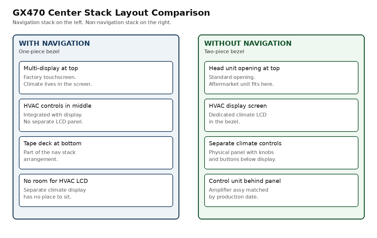
Navigation and Non-Navigation Center Stack Layouts
GX470 scope
This guide covers the GX470 from 2003 to 2009 with factory navigation as the starting truck and a GX470 built without navigation as the parts source. The removal order, the control assy service details, and the amplifier access details in this guide come from GX470 procedures for that generation. The owner walkthrough that supports the conversion steps covers the same generation, and the control unit bands in the matching chart run from November 2002 production through July 2009 production.
A truck that already has the separate climate panel and the two-piece bezel does not need this conversion.
GX460 scope note
The GX460 receives a scope note in this guide and no conversion procedure. Non-navigation GX460 trucks are rare early base models, and the published head unit guide notes that the one-piece center stack makes fitment harder on that generation. No GX460 conversion procedure is verified for this guide, so GX460 owners should use the head unit guide for interface and replacement options that keep the factory stack intact. This guide prints no GX460 part numbers, wire counts, or removal steps.
GX550 scope note
The GX550 receives a scope note in this guide and no conversion procedure. GX550 owners who want a different head unit arrangement should look for options that were designed for that truck and verified for that generation.
Parts and tools
Gather every part in this section and verify every part number match before the teardown starts.
| Part | What to check |
|---|---|
| Non-navigation climate control panel with its matched amplifier assy, salvage | The panel and the control unit work as a matched set for this job. Match the amplifier number printed on the unit to the production band in the matching chart. A verified used set for the earliest band: GX470 non-navigation climate control unit, 88650-60770 (eBay) |
| Bezel, Panel, Instrument Cluster Finish, Center 55412-60270 | The two-piece non-navigation panel with the climate display opening. The part shows as discontinued new, so salvage is the usual route. Confirm by VIN and by listing photos |
| Radio brackets, 86211-60170 and 86212-60170 | The genuine bracket pair that mounts the display and the head unit. Salvage controls can arrive without brackets, so confirm brackets in writing and in photos before payment |
| Dash kit, Metra 95-8166G | Double-DIN mounting kit for the 2003 to 2009 GX470 without factory navigation. Amazon alternate: Carxtc double-DIN dash kit for the 2003 to 2009 GX470 |
| Aftermarket head unit for the freed opening | A standard head unit fits after the conversion, and the walkthrough example used a 9 inch Android unit. Example of the class: ATOTO S8 Gen4 9 inch Android double-DIN stereo. The GX head unit guide carries head unit choice, CAN decoder selection, steering wheel controls, and backup camera retention in full |
| 18 AWG stranded wire, 6 colors | Extension stock for seven required runs plus the optional eighth, with slack for routing and loom |
| Heat shrink butt connectors, 320 pieces | Sealed crimp joints for the extensions and the illumination splice |
| Heat shrink tubing assortment, 580 pieces | Insulation over soldered joints |
| Wire harness tape | Loom protection for the extended runs where they pass trim edges and brackets |
| Push retainer clips kit for Toyota and Lexus, 345 pieces | Spare clips for any that break during garnish and panel removal |
| Tool | Used for |
|---|---|
| Plastic trim tool kit | Garnishes and finish panels that release on clips and claws |
| 1/4 inch drive socket and bit set, 46 pieces | The screws that hold the integration panel, the brackets, and the control assy |
| Klein Tools MM325 digital multimeter | Continuity checks on the extended wires and the illumination splice check |
| Soldering iron kit, 60W adjustable | Soldered extension joints with heat shrink |
| KAIWEETS self-adjusting wire stripper and crimper | Cutting and stripping the extension wires and crimping the sealed connectors |
| SEEKONE 350W mini heat gun | The heat source for heat shrink tubing and connector seals |
| Variable DC bench power supply, 0 to 30V | The bench test path for the salvage controls before fitting |
| Labels and a phone camera | Connector photos and labels before any connector is unplugged |
A Home Mechanic can source the matched set through car-part.com salvage listings, through a local salvage yard that will photograph the printed part number, or through eBay Motors salvage listings that show the unit label in the listing photos. A Home Mechanic can join the wire extensions with solder and heat shrink for the most compact joint, or with sealed crimp connectors and heat shrink where a soldering iron is not available, and either method needs a firm pull test and full insulation before the harness goes back behind the panel.
Match the control unit by production date
The control unit match is the single decision that owners warn about most directly. Owners report an owner-compiled list that was credited in the thread to a GXOR Facebook post, and the list assigns one control unit number to each production date band. Owners report that the wrong number will not work properly, so the match check belongs before payment and again on the bench when the salvage unit arrives.
Read the production date from the driver door jamb label on the truck that will receive the conversion. Find the month and year of production on that label and place the truck in one band in the chart. Then read the part number printed on the salvage control unit and confirm that the printed number matches the band for the truck. A seller photo that shows the printed label clearly is worth more than a listing title that names a model year range, because model year and production date do not line up in the same way during a switch-over.
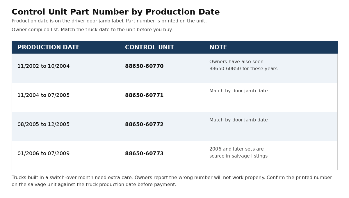
Control Unit Numbers by Production Date, Owner-Compiled List
| Production date | Control unit (amplifier assy) | Notes |
|---|---|---|
| 11/2002 to 10/2004 | 88650-60770 | Owners have also seen 88650-60B50 for these years. Verified used set: 88650-60770 climate control unit (eBay) |
| 11/2004 to 07/2005 | 88650-60771 | Match by the door jamb date and the printed number on the unit |
| 08/2005 to 12/2005 | 88650-60772 | Verified used set: 88650-60772 climate control unit (eBay) |
| 01/2006 to 07/2009 | 88650-60773 | 2006 and later sets are scarce in salvage listings |
The Lexus parts catalog carries the same four numbers as Amplifier Assy, Air Conditioner for the GX470. Its production ranges read 11/2002 to 11/2004 for 88650-60770, 08/2005 to 01/2006 for 88650-60772, and 01/2006 to 08/2009 for 88650-60773, so the catalog places two changeovers one month past the owner list. The switch-over month caution in this section covers those boundary months. The catalog also lists 88650-60A50 for Canada package trucks built 01/2004 to 10/2004. A Lexus parts listing quoted in the thread shows 88650-60770 replaced by 88650-60B50. All four amplifier numbers show as discontinued at LexusPartsNow as of November 2026, so the matched set comes from salvage for every band.
Trucks built in a switch-over month need extra care. Owners report that a truck built in a switch-over month is a crap shoot for matching, in the wording owners used in the thread. A Home Mechanic with a switch-over month truck should confirm the number with the seller, should keep the return terms in writing, and should run the plug-in test in the next section before any wire is cut. The test result carries more weight than a listing description when the production date sits on a band edge.
Scarcity changes the search for later trucks. Owners in 2025 posts call the 2006 and later control sets scarce, and one owner in a 2025 post reported 1 of 1 in the US on car-part.com for a 2006 and later set at the time of that search. A reader with a 2006 to 2009 truck should expect a longer search, should set alerts in the salvage listings, and should avoid starting the teardown until the matched set is in hand and tested. A reader with an earlier truck will usually find more listings, and the same verification steps still apply to every band.
The parts catalog settles the bezel question that the thread left open. Both bezel numbers are Panel, Instrument Cluster Finish, Center. The catalog lists 55412-60260 with an EMV equipment note for the navigation display trucks, and it lists 55412-60270 with no equipment note. Owners identify 55412-60270 as the 2003 to 2009 non-navigation bezel. A 60260 panel comes from a navigation stack and carries that stack’s openings, so a 60260 does not substitute for a 60270 in this conversion. LexusPartsNow shows 55412-60270 as discontinued and 55412-60260 as still orderable as of November 2026. Confirm the bezel by VIN with a parts counter or a trusted listing that checks fitment by VIN, and use photos that show the two-piece construction and the opening for the climate display to confirm that a listing is truly the non-navigation piece.
The radio brackets that come out with the multi-display carry catalog numbers of their own. Bracket, Radio No. 1 is 86211-60170 and Bracket, Radio No. 2 is 86212-60170, and a genuine new set was listed on eBay as of November 2026 in the parts table. Owners report that salvage controls can arrive without brackets, and owners ask whether the controls mount to the navigation brackets. Ask the seller to include the non-navigation brackets and to show them in the shipment photos. A conversion that reaches the fitting stage without brackets stops at that stage, and the Home Mechanic alternative of fabricating a bracket should be treated as a last resort that needs a test fit with the bezel before the dash goes back together.
Test the salvage controls before the final install
Owners list testing the salvage climate controls as its own step in the conversion, and the test protects every later step. A control unit that fails on the bench or in a plug-in test costs a return shipment. A control unit that fails after the wires are extended and the bezel is fitted costs a second teardown and a harder diagnosis, because the installer must then separate a bad unit from a bad extension joint.
A Home Mechanic has two practical test paths. The bench path powers the controls with a regulated 12V supply on the bench and checks that the panel lights, the display wakes, and the buttons and knobs respond in a consistent way. The bench path needs the correct power and ground pins identified before power is applied, and a Home Mechanic who cannot identify those pins with confidence should use the in-truck path instead. Applying power to the wrong pin can damage a scarce salvage unit, and that risk is a stop condition for the bench path.
The in-truck plug-in path connects the salvage controls in the truck before the final fitting and before the wire extensions are made permanent. The installer disconnects the battery, opens enough of the stack to reach the connectors, plugs the salvage panel and unit in, reconnects the battery for the test only, and checks the climate functions that the connectors in that temporary position can support. The installer then disconnects the battery again before continuing the teardown. This path uses the truck harness as the test fixture, and it confirms communication between the panel, the control unit, and the truck in a way a bench supply cannot fully repeat.
Record the test result in writing before the conversion proceeds. That record becomes the comparison point for the full climate test later in the job. A unit that shows a dead display or a dead fan control during the early test should go back to the seller under the return terms that the buyer kept in writing.
Stop conditions
Stop the job and resolve the issue before cutting wires or forcing trim when any condition in this section appears. The conversion is reversible in its early stages and becomes harder to reverse after the extensions are soldered and the bezel is changed.
- The production date and the control unit number do not match a band in the chart. Stop until the seller explains the mismatch with a printed label photo.
- The truck production date falls in a switch-over month. Stop until the plug-in test confirms the unit.
- The salvage order arrives without brackets. Stop until a confirmed bracket source is in hand.
- The bezel in hand is the one-piece navigation piece. Stop if the piece lacks the opening for the climate display.
- The salvage controls fail the bench test or the plug-in test. Stop and resolve the failure with the seller.
- A connector, a claw, or a clip breaks during removal. Stop until a replacement or repair is ready, because a loose panel will rattle and can stress the extended wires.
- The wiring in the truck does not match the expected connectors for the conversion. Stop and identify the equipment variant before any splice.
Conversion procedure in order
Work the steps in this section in order. The order moves from sourcing and testing to teardown, then to wiring, then to fitting, then to climate testing, and only then to the head unit. Skipping the climate test and fitting the head unit first buries the climate controls behind a second removal if a climate fault appears.
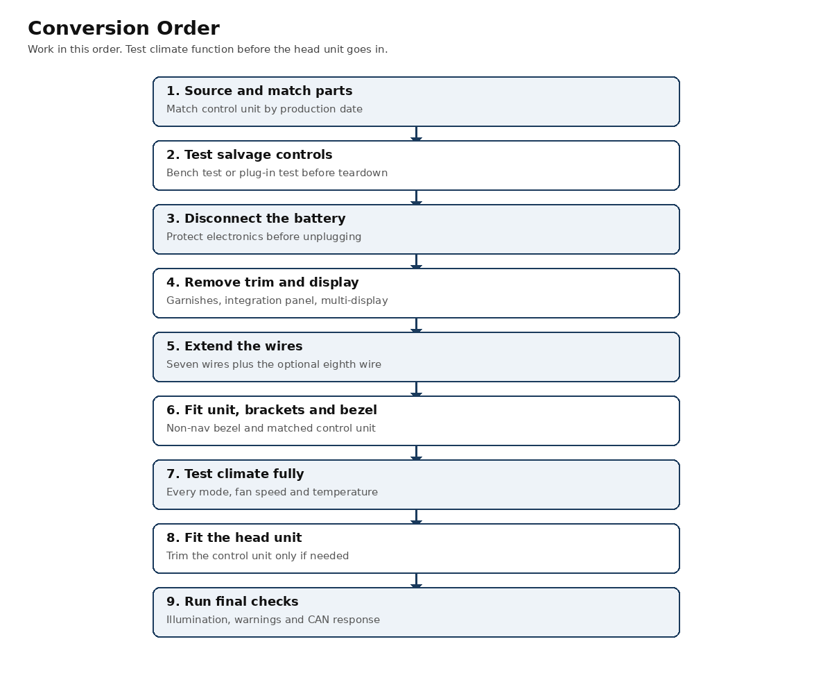
Conversion Work Order
Step 1: Source and match parts by production date
Read the production date on the driver door jamb label. Match the control unit number to the band in the chart and confirm the printed number on the salvage unit. Confirm the two-piece non-navigation bezel by VIN and by photos that show the climate display opening. Confirm that brackets are included or separately sourced. Confirm that the panel, the unit, the bezel, and the brackets are all in hand before Step 3 begins.
Step 2: Test the salvage controls first
Run the bench test with a 12V supply or the in-truck plug-in test as described in the testing section. Record the functions that work. Resolve any failure with the seller before the teardown deepens.
Step 3: Disconnect the battery
Park on a level surface, turn the truck off, and disconnect the negative battery cable. Protect the cable end so it cannot spring back onto the terminal during the work. Wait for the truck systems to go to sleep before unplugging modules, and treat every connector behind the stack as a live system connector until the battery is disconnected. The Truck Garage guide on dash warning lights, linked in this guide, helps a reader sort any warning light that appears after a battery disconnect and reconnect cycle.
Step 4: Remove the garnishes, the integration panel, and the multi-display in order
The removal order is console upper panel garnish No. 2 first, then console upper panel garnish No. 1, then instrument panel garnish LH, then instrument panel garnish RH, then the integration control and panel assy, then radio bracket No. 1, then radio bracket No. 2, then release the 2 claws and remove the multi-display. Work each garnish loose with plastic trim tools and keep each fastener with the piece it held. The integration control and panel assy comes out after its 3 screws are removed. Photograph every connector before unplugging it and label the connectors that look alike.
Step 5: Open the lower center finish area as needed for access
The instrument cluster finish panel center lower comes off after the 5 clips are disengaged, and the connectors behind it are disconnected after the panel is free enough to reach them. Keep the screws, clips, and claws for each panel in separate labeled containers.
Step 6: Remove the navigation climate arrangement and prepare the opening
Unplug the remaining stack connectors in the order they become accessible and note each connector position. Keep the factory harness intact apart from the extensions planned in Step 7. Correct any damaged loom or broken clip while the opening is empty.
Step 7: Extend the seven wires plus the optional eighth wire
Owners report that seven wires must be extended to reach the relocated controls and that one optional extra wire makes the job easier. Cut one wire at a time, extend that wire with a matching length that allows clean routing without tension and without excess bulk behind the panel, join the wire, insulate the joint, and label the run before moving to the next wire. Working one wire at a time prevents cross-connection errors that are hard to trace after the harness is loomed. Route the extended runs away from sharp bracket edges and away from the head unit cage, and secure the loom so the runs cannot chafe or pull on the connectors when the panel is fitted.
A Home Mechanic can solder each extension and cover the joint with heat shrink for a compact and durable connection. A Home Mechanic can also use sealed crimp connectors with heat shrink where soldering access is poor, and each crimp needs a firm pull test before the heat shrink is applied. Mixed methods are acceptable when each joint is insulated, strain relieved by the loom routing, and tested for continuity after the panel is fitted. Avoid twist-only joints and avoid tape-only insulation, because both methods fail behind a dash where heat and vibration work on the joint every drive.
Step 8: Take the panel illumination from the heater control switch connector
The navigation truck harness leaves the panel illumination circuit open at the connectors this conversion reuses. The amplifier terminal table assigns ILL+ at A13 pin 18 and ILL- at A15 pin 27 to non-navigation trucks, and the navigation truck fills A15 pin 27 with the R-B S-AUTO wire instead. The heater control switch connector H13 carries the same circuit in the same wire colors, and that connector comes free when the switch panel comes out. Take ILL+ from H13 pin 12 (wire G) and ILL- from H13 pin 22 (wire W-G), and join each feed to the matching panel wire with the same joining standard used for the extensions. Take the R-B S-AUTO terminal out of the A15 connector at pin 27 and tape that terminal back in the loom, because the non-navigation assembly reads pin 27 as ILL- and the S-AUTO wire has no function after the conversion. Confirm the tap with a multimeter before joining: H13 pin 12 reads 10 to 14 V against ground with the light control switch at TAIL or HEAD, and H13 pin 22 carries the dimmer return, so the panel lamps follow the rheostat after the tap. Test the illumination with the headlights or parking lights on before the bezel is fully seated, because correcting an illumination splice after the stack is closed requires reopening the same trim.
Step 9: Fit the control unit, the brackets, and the bezel
Mount the non-navigation brackets in the opening and confirm that each bracket sits flat without forcing the mounting screws. Fit the matched control unit to the brackets and connect the extended harness and the remaining connectors. Fit the climate control panel and confirm that the knobs and buttons move without binding against the bezel. Fit the two-piece non-navigation bezel and confirm that the climate display sits in its opening with an even gap and that the display is readable from the driver seat. The non-navigation air conditioner control assy in service form comes off with 2 screws, and the heater control housing work that sits behind it uses 2 screws and then 3 screws and the housing, with the control knob and the heater control name sheet as separate service parts and a replaceable control bulb. Those service details matter if a salvage panel arrives with a cracked housing, a missing knob, or a dead bulb, because each of those items can be addressed on the bench before the panel goes into the truck.
Amplifier access follows a separate path when the job requires it. Non-navigation amplifier access releases the 4 claw fittings and removes the 6 screws and the heater control housing, then disconnects the cable, then removes the 2 screws and the air conditioner amplifier assy. A separate amplifier replacement procedure starts from the passenger side through the front door scuff plate RH, the cowl side trim board RH, the instrument panel under cover No. 2, the glove compartment door sub-assy, and the instrument panel ornament.
Step 10: Run the climate full-function test before the head unit goes in
Reconnect the battery for the test. Start the truck and run the climate system through every mode, every fan speed, the full temperature range, the air conditioning request, the recirculation change, and the defrost modes. Confirm that the display shows each change, that the panel illumination works with the dash lights, and that the air delivery changes at the vents in the direction the controls command. Compare the result with the written record from the early salvage test. Resolve any climate fault at this stage, while the head unit opening is still empty and the connectors are still reachable.
Step 11: Fit the head unit and address trimming only if needed
Owners report that the climate control unit may need trimming so a 9 inch Android head unit fits, in an owner report from the walkthrough thread. Test fit the chosen head unit in the opening before any trimming is considered. Mark the contact point if the unit touches the control unit housing, remove the minimum material needed for clearance, and test fit again before final mounting. A smaller standard head unit may need no trimming at all, and trimming is a fitment correction for a specific large unit rather than a standard step for every conversion. Use the head unit guide linked in this guide for head unit choice, CAN decoder selection, steering wheel control retention, and backup camera retention, because that guide covers those decisions in full and this guide does not repeat that material.
Step 12: Run the final checks
Confirm that the climate system still passes the full-function test with the head unit powered. Confirm that the head unit powers, that the speakers play, and that the illumination dims as expected. One owner reported in a single owner report that the converted truck new head unit would not recognize the CAN bus after the conversion, with the cause unresolved in the captured text. Treat CAN recognition as a check item on the final list rather than as an expected failure, and use the head unit guide CAN decoder material if the check fails. Check for warning lights after the battery reconnect and use the dash warning lights guide linked in this guide to sort any light that stays on. Refit any remaining trim in the reverse order of removal, confirm that every garnish clip seats, and road test the truck with the climate system running in more than one mode.
What stops working
Two factory features stop working when the factory stereo is replaced, and the conversion includes that replacement. The glove box CD changer does not work after the factory stereo is replaced. The center console DVD player does not work after the factory stereo is replaced. Both losses are documented in the published Truck Garage head unit guide, and a reader who values either feature should weigh that loss before starting the conversion or should choose one of the alternative paths in the next section.
The factory navigation screen and its menus leave with the multi-display. Climate display moves to the non-navigation panel display, and navigation moves to the new head unit when the owner chooses a unit with that function.
Alternatives that keep the factory stack
Three alternative paths give an owner modern functions without the full conversion, and each path keeps a different part of the factory arrangement. The interface module path keeps the nav stack and adds an interface module of the Grom VLine type, which brings modern app and phone functions to the factory display while climate control stays in the factory screen. Owners who choose this path avoid the salvage hunt, the wire extensions, and the bezel change, and they keep the CD changer and console DVD question separate from the head unit decision.
The CAN-decoder Android path keeps the nav stack and fits a CAN-decoder Android unit that drives the factory climate display. That path depends on the decoder correctly carrying climate commands and display data for the specific truck, so a buyer should verify decoder compatibility by truck year and equipment before purchase. Owners who choose this path should confirm steering wheel control and backup camera behavior with the seller in writing, because those functions travel through the same decoder.
The retained display board path fits an Android unit and retains the factory display circuit board behind it. Rhino Radios GX 470 installation notes describe removing the board from the factory display and leaving it connected so air conditioning stays active with temperature display. That path keeps the factory climate electronics in the loop while the visible screen changes, and it requires careful board handling and secure mounting so the retained board cannot short or rattle behind the new unit.
The full conversion in this guide remains the path that separates climate control from the head unit in hardware. A reader who wants climate control that works with any standard head unit, including a future head unit change, gains that separation from the conversion. A reader who wants the smallest change to a working truck will usually prefer one of the three alternatives in this section.
Troubleshooting after the conversion
A climate function that worked in the early salvage test and fails after fitting points first to the extension work and the connector seating. Check each extended wire for continuity, check each joint for insulation damage, and confirm that every connector behind the panel is fully seated with its lock engaged. Work the climate test again after each correction so the change that fixed the fault is known rather than guessed.
A climate display that stays dark while the fan and temperature controls work points to the display power, the illumination splice, or the panel bulb. The non-navigation control assy uses a replaceable control bulb, so a dark panel can sometimes be corrected without replacing the whole panel. Confirm 10 to 14 V at H13 pin 12 with the light control switch at TAIL or HEAD before blaming the tap.
A head unit that will not fit flush points to bracket position, harness bulk behind the unit, or control unit clearance for a large screen unit. Reroute the extended loom to the side of the opening, confirm that the brackets sit flat, and test fit again before any trimming is done. Owners report trimming the climate control unit for a 9 inch Android unit as an owner report, and that correction should remove only the material that the test fit marks as contact.
A head unit that does not recognize the CAN bus after the conversion appeared as a single owner report with the cause unresolved. Check the decoder connections, the head unit CAN settings for the truck, and the harness connectors before replacing parts. Use the head unit guide for decoder and steering wheel control material, and record whether the climate system still passes its full test while the CAN fault is present, because a passing climate test separates a head unit communication fault from a climate control fault.
Warning lights that appear after the battery disconnect need a connector check before parts are ordered. Confirm that every connector removed during the job is reconnected and use the dash warning lights guide linked in this guide to identify any light that remains.
Panel rattles after the refit point to a broken clip, a claw that did not seat, or a bracket screw that was left loose. Open only the garnish or panel that covers the rattle, correct the clip or claw, and refit that piece before reopening the whole stack.
Cost and time planning
Owner reports give a wide cost range because salvage supply and bracket inclusion change the parts total for each truck.
| Parts set | Report | Cost |
|---|---|---|
| Climate controls, bezel, and brackets from a Texas salvage yard | Owner report, 2019 | $225 shipped |
| HVAC controls alone through car-part.com salvage listings | Two owner reports, October 2025 | $250 shipped |
| Parts pieced together separately, plus the head unit | Owner estimate, 2018 era | About $1,900 |
The spread between the 2019 salvage figure and the 2018-era pieced-together estimate shows why salvage sourcing and bracket confirmation drive the total cost of this job. A buyer should budget for the head unit, the dash kit or mounting solution, wire and joining supplies, trim clips for any that break, and return shipping protection on the salvage set.
Time planning should allow a full day for a first conversion with testing at both ends of the job.
Related Truck Garage guides
Read the GX head unit guide at https://thetruckgarage.com/gx-head-unit-guide/ for head unit choice, CAN decoder selection, steering wheel control retention, and backup camera retention. That guide also documents the CD changer and console DVD losses that this guide lists in the section on what stops working.
Read the GX470 speaker replacement guide at https://thetruckgarage.com/gx470-front-door-woofer-and-cargo-subwoofer-replacement/ for trim and panel work habits that carry over to garnish and finish panel handling in this conversion.
Read the dash warning lights guide at https://thetruckgarage.com/dash-warning-lights-guide/ for post-conversion warning light checks after the battery disconnect and the stack work.
Sources
- GX470 factory manuals
- LexusPartsNow, genuine part pages for the amplifier assy and the instrument cluster finish center panel, https://www.lexuspartsnow.com/
- IH8MUD, Nav to Non-Nav Conversion Walkthrough, https://forum.ih8mud.com/threads/nav-to-non-nav-conversion-walkthrough.1141114/
- Rhino Radios, GX 470 Installation Notes, https://rrcs.zendesk.com/hc/en-us/articles/360043278212–GX-470-Installation-Notes
- The Truck Garage, GX Head Unit Guide, https://thetruckgarage.com/gx-head-unit-guide/
- The Truck Garage, GX470 Front Door Woofer and Cargo Subwoofer Replacement, https://thetruckgarage.com/gx470-front-door-woofer-and-cargo-subwoofer-replacement/
- The Truck Garage, Dash Warning Lights Guide, https://thetruckgarage.com/dash-warning-lights-guide/
FAQ
Does the conversion let any standard head unit fit a nav GX470?
Owners report that the conversion fits the salvage non-navigation climate controls with their brackets and the non-navigation bezel, and that any standard head unit then fits the freed opening. The walkthrough example used a 9 inch Android unit as an owner report, and owners report that the climate control unit may need trimming for that large size. A smaller standard unit may fit with no trimming, and every unit needs a test fit before final mounting.
How do I know which control unit my truck needs?
Read the production date on the driver door jamb label and match that date to the band in the chart in this guide. Owners report the owner-compiled bands as 88650-60770 for 11/2002 to 10/2004, 88650-60771 for 11/2004 to 07/2005, 88650-60772 for 08/2005 to 12/2005, and 88650-60773 for 01/2006 to 07/2009. The Lexus parts catalog carries the same four numbers as Amplifier Assy, Air Conditioner. Confirm the number printed on the salvage unit itself, because owners report that the wrong number will not work properly.
What happens if my truck was built in a switch-over month?
Owners report that trucks built in a switch-over month are a crap shoot for control unit matching. Keep the seller return terms in writing, confirm the printed number on the unit, and run the bench test or the in-truck plug-in test before any wire is cut. The test result should decide whether that unit stays or goes back.
How many wires need to be extended?
Owners report that seven wires must be extended to reach the relocated controls. Owners also report one optional extra wire that makes the job easier, so most installers will prepare for eight runs. Extend one wire at a time, join and insulate each run, and route the loom away from sharp edges and the head unit cage.
Where does the panel illumination feed come from?
The feed comes from the heater control switch connector H13, which comes free when the switch panel comes out. H13 pin 12 carries ILL+ on the G wire and pin 22 carries ILL- on the W-G wire, the same circuit and the same wire colors the non-navigation panel uses. Confirm 10 to 14 V at pin 12 with a multimeter with the light control switch at TAIL or HEAD, and test the panel illumination before the bezel is fully seated. Correcting the tap after the stack is closed requires reopening the same trim.
What stops working after the conversion?
The glove box CD changer and the center console DVD player do not work after the factory stereo is replaced. The factory navigation display and its menus also leave with the multi-display, and climate display moves to the non-navigation panel. A reader who needs the changer or the console DVD should consider the alternative paths that keep the factory stack.
Can I test the salvage controls before I tear the truck apart?
Owners list testing the salvage climate controls as its own step, and a Home Mechanic can run a bench test with a 12V supply or an in-truck plug-in test. The in-truck test confirms communication with the truck harness, and the bench test needs the correct power and ground pins identified before power is applied. Record the functions that work so the later full climate test has a comparison record.
Are the parts easy to find for a 2006 to 2009 truck?
Owners in 2025 posts call the 2006 and later control sets scarce, and one owner in a 2025 post reported 1 of 1 in the US on car-part.com at the time of that search. Expect a longer search for a later truck, set alerts in the salvage listings, and keep the matched set in hand and tested before the teardown starts. Prices from owner reports were $250 shipped for the HVAC controls in October 2025, compared with $225 shipped for controls, bezel, and brackets in 2019.
Leave a Reply