The GX470 and the GX460 stop with an integrated hydraulic brake booster. An electric pump motor pressurizes brake fluid, and an accumulator stores that pressurized fluid in a sealed canister at the booster. Stored pressure is the power assist. When you press the pedal, the booster applies assist from the stored pressure, and the pump runs again to replace what you used.
The master cylinder is in the same assembly. The master cylinder solenoid includes the skid control ECU, and the ECU runs the pump through a relay built into the solenoid. An accumulator pressure sensor reports the stored pressure to the ECU, which starts the pump when pressure falls and stops it when pressure recovers. The same assembly feeds the anti-lock, traction, and stability functions, so a power supply fault reaches further than pedal feel.
Four parts do the work that this guide tests. The reservoir holds the fluid supply. The pump motor runs the pump that charges the system. The accumulator holds the charge between pump runs. The booster and master cylinder spend the charge as pedal assist and as pressure to the wheel lines. When the ECU decides the power supply side has failed, it turns on the brake warning light and sounds the skid control buzzer, the dash alarm in the title of this guide.
A healthy system holds pressure over a long drive, and the pump runs in short charges. A system that loses pressure runs the pump again and again to keep up.
A pulsing or vibrating pedal under hard braking is a different complaint, and it is covered in the brake pulsation guide: GX Brake Pulsation Diagnosis. This guide covers the booster power supply side.
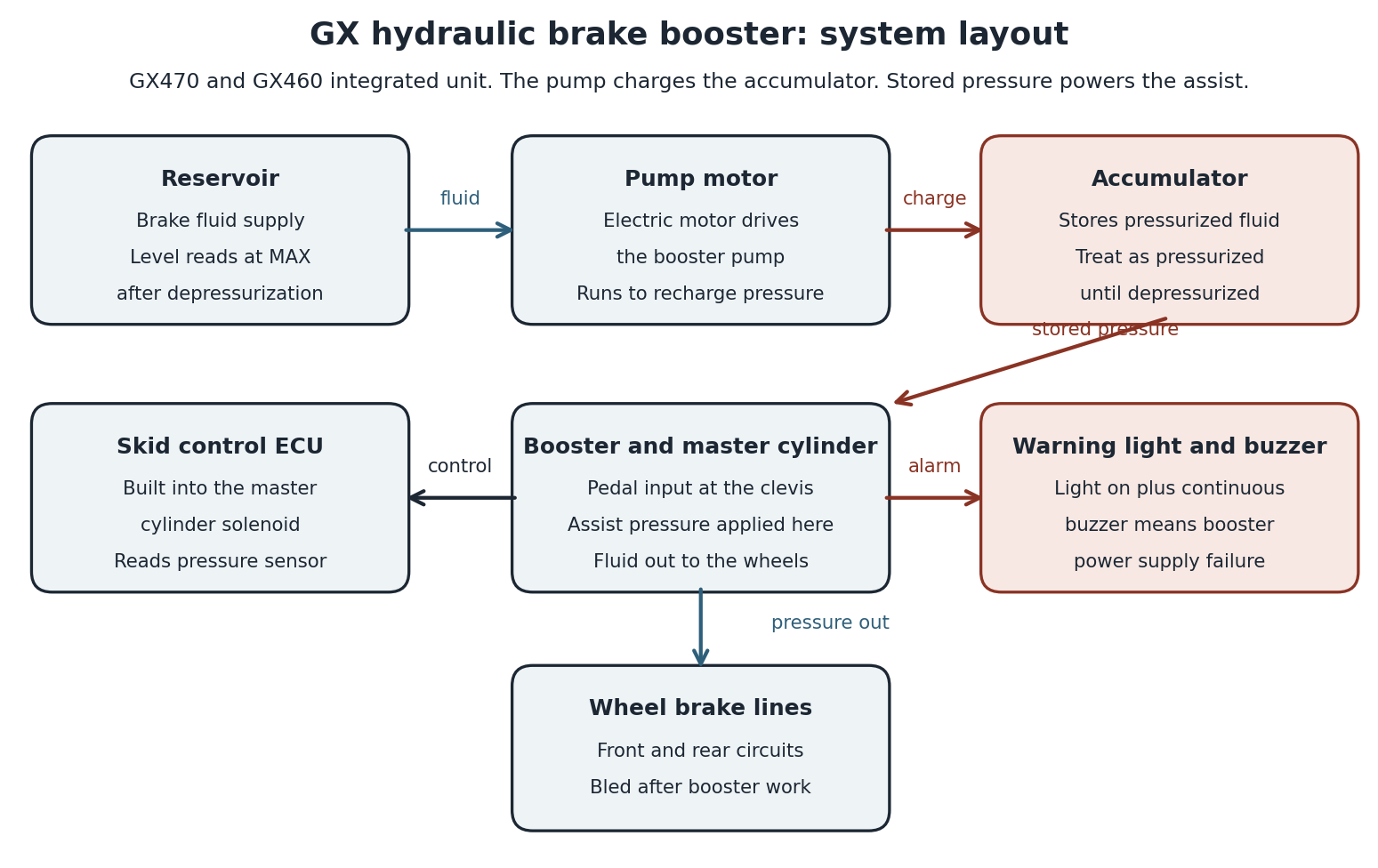
System layout. The pump charges the accumulator, the accumulator powers the assist, and the ECU turns on the warning light and the buzzer.
Parts and tools
Read the diagnosis sections before you order parts. The checks name the failed part first.
| Item | Used for |
|---|---|
| Brake fluid, SAE J1703 or FMVSS No. 116 DOT 3 | Topping up and the bleed steps, on both the GX470 and the GX460. |
| Phone stopwatch or a watch with a seconds hand | Timing pump runs in the counted and timed tests |
| Digital multimeter | Battery voltage check and pump motor resistance check |
| Scan tool with Lexus ABS and VSC coverage | Reading the C1251 to C1257 chassis codes, which an engine-only reader cannot read |
| Flare nut wrench set | Brake tube union nuts and actuator tube nuts, gripped without rounding |
| Torque wrench covering 8 to 42 ft lbf (11 to 57 Nm) | Booster, accumulator, solenoid, and tube fasteners |
| Torque driver or small torque wrench covering 15 to 69 in lbf (1.7 to 7.8 Nm) | Wire harness screws, pump pin, pump bracket, and reservoir fasteners |
| Vinyl tube and a catch bottle | Caliper bleeder work during the line bleed |
| Bench vise, a saw, shop rags, and protective glasses | The accumulator disposal step |
| Jack and jack stands | Raising the truck for caliper bleeder access during the line bleed |
Shop level items that most owners borrow from a shop: the LSPV gauge set, SST 09709-29018, and a brake pedal effort gauge for the fluid pressure change inspection, and a tester that can run the solenoid active test for the solenoid bleed and the full system air bleed. The listening checks, pedal tests, code read, and timed pump runs come first in this guide. The gauge work is the confirmation step.
Replacement parts to have only when a check calls for them are in the table below, with the genuine part numbers from the Lexus parts catalog. The table prints the catalog number for each year band. Order by the number printed for your truck and year. The parts diagrams at parts.lexus.com show the assembly breakdown for your truck.
| Part | Genuine number | Fits |
|---|---|---|
| Hydraulic brake booster assembly, with master cylinder | 47050-60080 | GX470, 2003 |
| Hydraulic brake booster assembly, with master cylinder | 47050-60111 | GX470, 2004 to 2009 |
| Hydraulic brake booster assembly, with master cylinder | 47050-60410 | GX460, 2010 to 2012 |
| Hydraulic brake booster assembly, with master cylinder | 47050-60570 | GX460, 2013 to 2014 |
| Hydraulic brake booster assembly, with master cylinder | 47050-60571 | GX460, 2015 to 2018 |
| Hydraulic brake booster assembly, with master cylinder | 47050-60A10 | GX460, 2019 to 2023 |
| Booster pump motor | 47960-30030 | GX470, 2003 |
| Booster pump motor | 47960-60090 | GX470, 2004 to 2009 |
| Booster pump motor | 47960-60050 | GX460, 2010 to 2023 |
| Brake booster pump assembly with accumulator | 47070-30060 | GX470, 2003 |
| Brake booster pump assembly with accumulator | 47070-60030 | GX470, 2004 to 2009 |
| Brake booster pump assembly with accumulator | 47070-60050 | GX460, 2010 to 2023 |
| Accumulator | 47950-30010 | GX470, 2003 |
| Accumulator | 47950-60020 | GX470, 2004 to 2009; GX460, 2010 to 2020 |
| Master cylinder solenoid | 47217-60021 | GX470, 2004 to 2009 |
| Master cylinder solenoid | 47217-60110 | GX460, 2010 to 2011 |
| Master cylinder solenoid | 47217-60341 | GX460, 2012 to 2014 |
| Master cylinder solenoid | 47217-60501 | GX460, 2015 to 2018 |
| Master cylinder solenoid | 47217-60760 | GX460, 2019 to 2023 |
Failure symptoms
The pump cycles often. The pump runs to restore pressure after every use, so some cycling is the system working. The failure pattern is cycling that keeps shortening. One 2009 GX470 owner in the ClubLexus buzz and noise thread traced two small signs to the accumulator: the headlights dimmed about every 9 seconds at idle and the idle bumped at the same interval, matching the pump drawing current on each cycle. A dealer inspection found nothing. The cycling later shortened to about every 3 seconds, a squeak joined it, and brake power never changed. The repair that ended it gets its own section later in this guide. Cycling that keeps shortening means the system is losing stored pressure between runs.
The pump runs long. A pump that runs and runs is trying to reach a pressure it cannot reach or cannot confirm. The code family sets a threshold for this pattern: power supplied to the pump motor for more than 5 minutes sets code C1252 on the GX470, and motor operation of 3 minutes or more sets the same code on the GX460. Treat any run that extends toward minutes as a stop and diagnose event.
The pedal goes hard. Stored pressure is the assist, so a system that cannot build or hold pressure gives the assist back. The pedal asks for much more leg force to produce the same stop, and stopping distances grow. A hard pedal can arrive suddenly when the pump or its drive circuit quits, or creep in as the accumulator fades. Either pattern is a stop condition, covered in the next section.
The warning light comes on and the buzzer sounds continuously. The brake warning light on together with the skid control buzzer sounding points to the brake master cylinder power supply system. Two normal behaviors clear on their own. The warning light may stay on for about 60 seconds after the ignition turns on and then turn off. Repeated pedal presses may turn the light and the buzzer on, and both stop after a few seconds. A light and buzzer that stay on, or that return during normal driving, are the failure report. The dash warning lights guide covers the rest of the GX warning light set: Dash Warning Lights Guide.
Codes are stored. Most trucks that reach the warning light and buzzer also store one or more codes from the C1251 to C1257 family. Some trucks cycle badly and store nothing at first. The code section below gives each code its meaning.
Stop conditions
Do not drive with the warning light on and the buzzer sounding continuously. If the booster fails during driving, the brake system warning light comes on and the buzzer sounds continuously, and the brakes may not work properly. Press the pedal firmly, stop the truck in a safe place, and arrange service or a tow.
Do not keep driving on a hard pedal. A hard pedal means the assist is gone or going. Park the truck and run this diagnosis in place, or have it moved.
Depressurize the accumulator before opening anything. The accumulator holds pressurized fluid after the engine stops, until you release it. Opening a booster joint, a tube, or the accumulator itself against stored pressure sprays brake fluid and can injure hands and eyes. The release step comes before any wrench work in this guide: turn the ignition off and press the brake pedal until the reaction force goes light and the stroke gets longer. The counted version of that step in the inspection procedures is more than 40 presses, and the tests section below uses that count.
Treat every removed accumulator as pressurized until it is discharged. A removed accumulator still holds pressure and gas. The disposal step in the replacement section discharges it in a vise, under a rag, with eye protection.
Keep brake fluid off paint. Cover the fender area before you open any joint, and wash contact off with water right away.
First observations
Run these three observations in order and write down what you find.
1. Listen to the pump cycle pattern. Turn the ignition on with the engine off in a quiet place and listen. It runs to charge the accumulator and then stops. Note how long the first run lasts, whether the pump restarts with the truck untouched, and what a few pedal presses do to the cycle interval. Pump runs that pull the headlights down and bump the idle at a steady interval, as in the owner report above, confirm the pump is doing the cycling. A pump that never runs points at the motor, its feed, or its drive circuit.
2. Check the fluid level the counted way. The reservoir level is accurate only with the accumulator depressurized, because a charged accumulator holds fluid that is part of the reservoir count. Turn the ignition off, press the pedal more than 40 times until the stroke lengthens, and then check the level. If the level is below the mark, check every booster joint, tube, and caliper for leaks. Top up only after the counted check, with SAE J1703 or FMVSS No. 116 DOT 3 fluid.
3. Check the battery voltage. The booster inspection standard is battery voltage of 11 to 14 V. Charge or test the battery first. Measure the voltage at the battery posts before you decide any booster part has failed. Charge or correct the battery when the reading falls outside that range. A truck that drains overnight is covered in the parasitic drain diagnosis as a separate hunt: GX Parasitic Battery Drain Diagnosis. Finish the battery question first, because the timed tests assume full voltage.
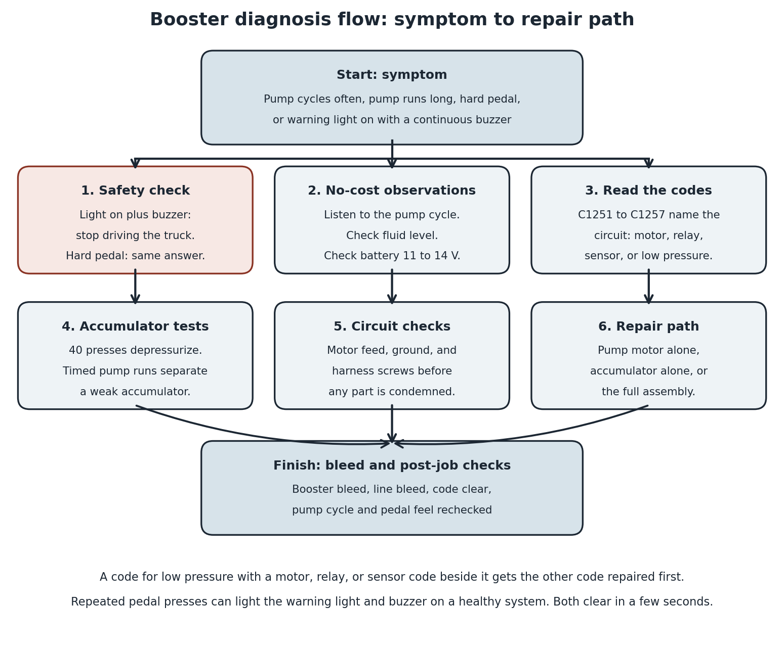
Diagnosis flow. The safety check and the first observations come before the code read, and every repair path ends at the same bleed and post-job checks.
Pull the codes
Pull the chassis codes before you buy anything. The booster family lives in the ABS and VSC system, so the reader has to cover that system. Many entry level readers cover engine codes only and will report a clean truck while these codes are stored. Record every code before you clear anything.
Pulling the codes without a reader. The skid control ECU flashes these codes on the dash warning lights when two terminals in the DLC3 port are connected. A short jumper wire or a paperclip makes the connection. Toyota sells the same connection as a check wire, SST 09843-18040.
- Turn the ignition off and find the DLC3 port under the driver side of the dash. Connect terminal 13 (TC) to terminal 4 (CG) with the jumper wire.
- Turn the ignition switch to ON. On the GX460, turn the engine switch on (IG).
- Count the flashes on the warning lights. On the GX470, the ABS and VSC TRAC warning lights flash the codes. On the GX460, the ABS warning light and the slip indicator light flash the codes.
- Each code is two digits. The light flashes the first digit, pauses 1.5 seconds, and flashes the second digit. A pause of 2.5 seconds separates one code from the next, the codes come in ascending order, and the full set repeats after a 4 second pause. Match the number to the Blink number column in the tables below.
- A light that flashes on and off in even 0.25 second intervals with no pauses is showing the normal code. No code is stored.
- Write down every number, then remove the jumper wire and turn the ignition off.
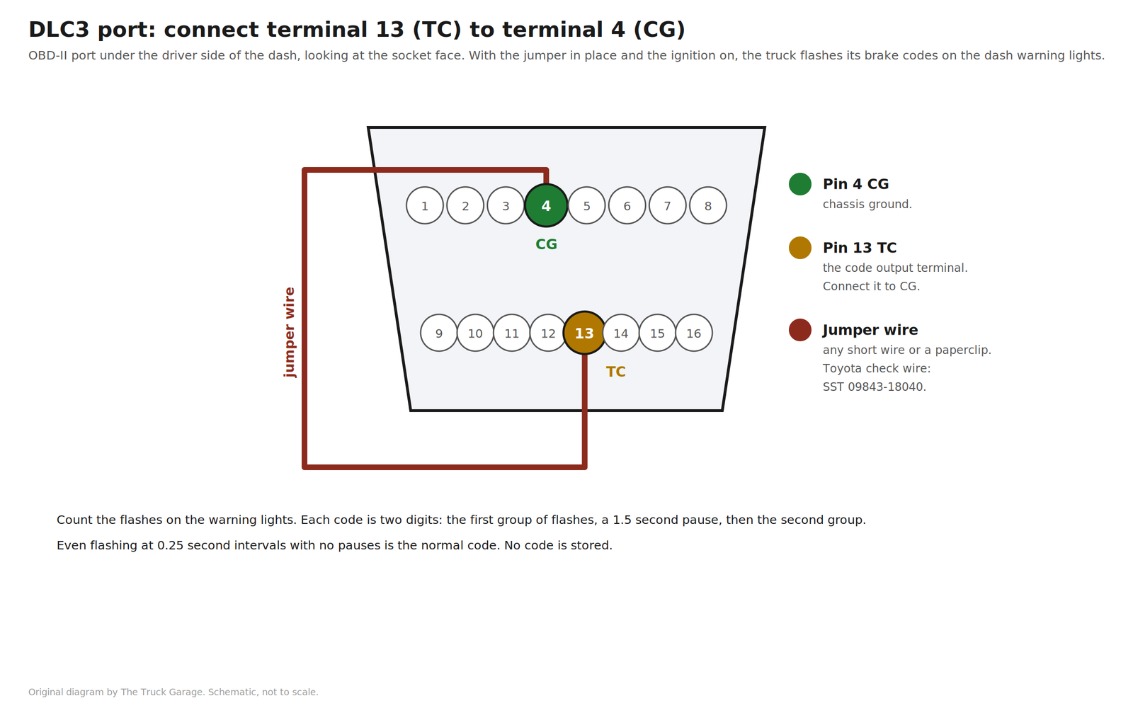
DLC3 port. The jumper wire connects terminal 13 (TC) to terminal 4 (CG).
Clearing the codes without a reader.
- Connect terminal 13 (TC) to terminal 4 (CG) again, and turn the ignition on.
- Press the brake pedal 8 times or more within 5 seconds.
- Check that the warning light flashes the normal code, the even 0.25 second flashing, then remove the jumper wire.
Disconnecting the battery cable does not clear these codes.
The table below is the 2005 to 2009 GX470 code set. The GX460 uses the same code family, and the rows where its meanings differ are printed in the GX460 section. The 2003 and 2004 GX470 runs an earlier version of the system with pressure switches, and its code meanings are in their own table further down.
| Code | Blink number | Meaning | First checks |
|---|---|---|---|
| C1251 | 51 | Pump motor is locked, or an open circuit in the pump motor ground. Detection is an open in the motor system circuit. | Pump motor connections, the two wire harness screws between the solenoid and the pump, and the motor resistance check in the repair paths section. |
| C1252 | 52 | Brake booster pump motor on time abnormally long. Power has been supplied to the pump motor for more than 5 minutes. | The pump motor, its circuit, and the accumulator pressure sensor. The timed tests separate a weak pump from a blind sensor. |
| C1253 | 53 | Hydro-booster pump motor relay malfunction, at the motor input circuit. | The relay is built into the master cylinder solenoid, so this code points at the solenoid and its feed. No plug-in relay under the hood serves this circuit. |
| C1254 | 54 | Accumulator pressure sensor malfunction. Fluid pressure does not change when the pump operates. On 2007 to 2009 trucks the detection condition adds: or when the brake is applied. | The pressure sensor inside the master cylinder solenoid, and confirmation that the pump runs and builds pressure while the sensor reports nothing. |
| C1256 | 56 | Accumulator low pressure malfunction. Stored pressure is below the standard value. | The accumulator, the pressure sensor, and the pump motor. |
| C1257 | 57 | Power supply drive circuit malfunction. The detection condition is an open in the motor system circuit, at the motor input circuit. | The drive circuit inside the master cylinder solenoid and the wiring between the solenoid and the pump. |
On 2005 to 2009 trucks, two repair order rules govern combined codes. When C1256 arrives with C1251, C1253, or C1254, repair the area the other code points to first, because a motor, relay, or sensor fault produces a false low pressure report on its own. When C1252 arrives with C1253, C1254, or C1256, repair the other code first for the same reason. Clear the codes only after the repairs, then rerun the observations.
The 2003 and 2004 code set
The 2003 and 2004 GX470 watches the same booster with pressure switches, one high pressure switch and one low pressure switch, where the later trucks use a pressure sensor. The code numbers are the same, and four of the meanings change.
| Code | Blink number | Meaning on 2003 and 2004 trucks | First checks |
|---|---|---|---|
| C1251 | 51 | Pump motor circuit fault, detected by current: more than 28 A flows to the motor for more than 1 second, or a current change of less than 7 A is detected more than 3 times while the motor runs. | The pump motor, checked at the master cylinder connectors: battery positive to terminal BM1 or BM2, negative to GND1 or GND2, and confirm the motor operates. |
| C1252 | 52 | Brake booster pump motor on time abnormally long. Power has been supplied to the pump motor for more than 5 minutes. This meaning matches the later trucks. | The pump motor, its circuit, and the pressure switches. |
| C1253 | 53 | ABS or TRAC motor relay fault: an open in the relay coil, a relay that stays on or never turns on, or a welded relay contact. | The ABS or TRAC motor relay and its circuit, then the pump motor circuit. On these trucks the relay is a separate part, outside the solenoid. |
| C1254 | 54 | Pressure switch circuit fault: a short or open in the low pressure switch, or an open in the high pressure switch, lasting more than 1 second. | The two pressure switches and their wiring. |
| C1256 | 56 | Accumulator low pressure. The suspect list is the accumulator, the high and low pressure switches, and the pump motor. | The accumulator, the pressure switches, and the pump motor. |
| C1257 | 57 | An open or short in the power supply drive system inside the ECU, lasting more than 1.5 seconds. | The ECU power supply drive circuit and its wiring. |
A truck with the warning light and buzzer on and no stored codes still gets the full observation and test sequence. A clean code read does not close this diagnosis.
The accumulator tests
The accumulator has one job: hold pressure between pump runs. These tests measure that job with a pedal count and a stopwatch. Run the battery check first, because a weak battery fails them for the wrong reason.
The depressurization check, more than 40 presses. Turn the ignition off and press the brake pedal more than 40 times. As the stored pressure releases, the reaction force at the pedal goes light and the stroke gets longer. This step opens the fluid pressure change inspection, which goes on with the LSPV gauge set, SST 09709-29018, and a brake pedal effort gauge. The gauge half is shop work for most owners. Any owner can run the pedal half: a pedal that never goes light and long is holding pressure it should release, and a pedal that starts light and long never stored pressure at all. Record the result: normal release, no release, or nothing stored.
The GX470 bleed test, a pump run of 8 to 14 seconds. This timed value applies to one test condition only, on 2005 to 2008 trucks. It is the check that closes the booster bleed procedure, which applies only when the brake booster with accumulator pump assembly has been removed and installed. The sequence runs: ignition off, press the pedal 20 times or more, press the pedal fully 10 times, then turn the ignition on and let the pump start. The pump run from that fully emptied state is 8 to 14 seconds. A run outside that window sends you back to repeat the bleed steps and recheck the time. Use this value only inside its condition: a pump refilling an emptied system after service. Owners in forum threads quote a motor run figure of 30 to 40 seconds for this booster family. That figure is an owner report.
The 2009 GX470 bleed check. The 2009 procedure has no timed pump run. After booster service, the 2009 truck gets the line bleed in the bleed summary, then the Techstream Air Bleeding utility, which runs the solenoids line by line. The utility protects the solenoids from overheating: a solenoid stops automatically in 4 seconds and does not respond again for an additional 20 seconds.
How the results combine. Frequent cycling at rest, long timed runs, and a C1256 low pressure code together describe a system that cannot hold or build stored pressure. The circuit checks in the repair paths separate a weak pump from a faded accumulator: a motor that passes its checks while the timed runs stay long leaves the accumulator as the part that cannot hold its charge. Short or absent pump runs with motor circuit codes describe an electrical failure, and the accumulator is not the suspect until the motor runs correctly and the timed tests still fail.
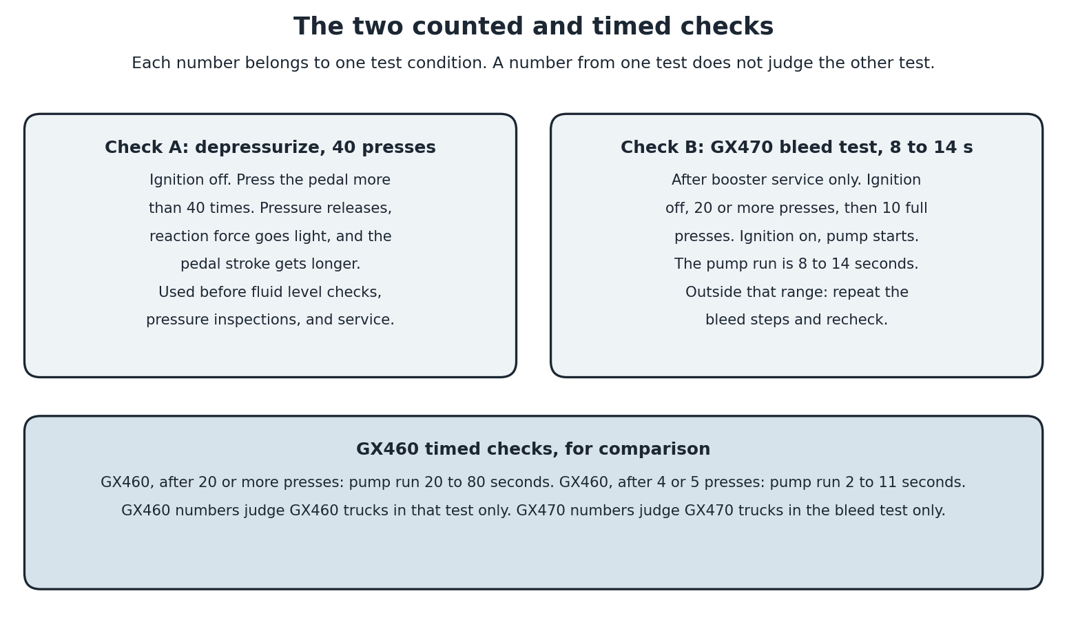
The counted and timed checks. Each number applies to its test condition and its model.
The owner-reported plunger, spring, and O-ring case
One documented owner repair is included in this guide because it matches the most common early symptom here, frequent cycling with no code and no loss of brake power. In the ClubLexus thread in the Sources section, a 2009 GX470 cycled its accumulator about every 9 seconds and later about every 3 seconds, dimming the headlights and bumping the idle on each cycle, with a cabin squeak and full brake power throughout. A dealer inspection found nothing. The owner traced the leak down to a small plunger, spring, and O-ring set under the accumulator canister, released the pressure first by pumping the pedal, replaced the small parts, and reported the cycling cured for about $11 in parts. Other owners in the thread confirmed the repair.
This case is an owner report from one thread, with confirming comments. The case explains a leak path the code family cannot see: a slow internal leak past a small seal cycles the pump without setting a code while the pump still keeps up. A truck that cycles often, holds a firm pedal, and stores no codes has a cheap documented branch to investigate before the accumulator or the full assembly enters the conversation. Depressurize before opening that canister area, because the canister is on the pressurized side of the system.
Repair paths
Four paths cover the failures this diagnosis finds. Pick the path from the codes, the timed tests, and the circuit checks together, because the assembly comes apart in sections.
Path 1: the pump motor alone. Choose this path when the motor itself fails its checks: it does not run, it runs weakly, or its circuit codes lead back to it. The bench inspection is direct. On 2005 to 2009 trucks, with the assembly removed, connect the positive battery lead to the red cable of the pump motor and the negative lead to the black cable, and check that the motor operates. The paired wire harness check measures resistance between the red wire and the black wire at the solenoid connection: the standard is 2 ohms. On 2003 and 2004 trucks, the operation check runs at the master cylinder connectors instead: battery positive to terminal BM1 or BM2, negative to GND1 or GND2. Before you replace the motor on any year, check the two screws that secure the wire harness. The motor feed passes through those screws, and their torque is 26 in lbf (2.9 Nm) on both models and all years. Tighten the screws if they are loose.
Path 2: the accumulator alone. Choose this path when the motor passes its checks, the codes point at low pressure, and the timed runs stay long: the pump works, and the storage fades. The accumulator unbolts from the pump, and the joint torque is 40 ft lbf (54 Nm) on 2003 and 2004 GX470 trucks, 42 ft lbf (57 Nm) on 2005 to 2009 GX470 trucks, and 42 ft lbf (57 Nm) on the GX460, with a new O-ring at the joint. Support the assembly in a vise, keep foreign matter out of the openings, and remove the accumulator pipe and spring with the canister when your assembly has them. Handle the removed accumulator under the disposal rule in the replacement section.
Path 3: the full assembly. On 2005 to 2009 trucks, choose this path when the fault lives in the solenoid side of the unit: the C1253 relay fault, because the motor relay is built into the solenoid; the C1254 pressure sensor fault, because the sensor is part of the solenoid; the C1257 drive circuit fault; or several of those faults at once. On 2003 and 2004 trucks, work the C1253 external relay and the C1254 pressure switches first, because those parts are outside the assembly on the early trucks. Cost figures appear in the FAQ. Plan on zero point calibration after any solenoid or booster replacement, and plan on the full bleed sequence.
Path 4: a used assembly, with cautions. Used booster assemblies trade at a fraction of new assembly prices, and the owner case in the FAQ quotes a price from about 11 years ago. The cautions are specific to this part. The accumulator charge state of a used unit is unknown, and a used accumulator can arrive already faded, which puts you back at the cycling symptom with the labor spent twice. Pump wear is unknown for the same reason. Match the unit by VIN, bench check the motor on arrival, and keep your old assembly until the truck passes the post-job checks.
Replacement overview
This overview groups the booster job into stages so the order is clear before you start. Work clean throughout, and cap or cover every port you open.
Stage 1: prepare the truck. Depressurize the accumulator with the counted release: ignition off, press the pedal more than 40 times, and confirm the light reaction force and the long stroke. Cover the painted surfaces, and have the catch bottle, rags, and caps ready.
Stage 2: remove the assembly. Disconnect the electrical connectors at the booster, including the fluid level warning switch connection. Disconnect the brake tubes with a flare nut wrench, and cap each tube as it comes off. Release the pedal connection at the clevis inside the cabin, then remove the mounting nuts and draw the assembly out.
Stage 3: split the assembly on the bench. Secure the assembly in a vise. Separate the parts your repair path calls for: the accumulator from the pump, the pump from the master cylinder, and the solenoid from the master cylinder body. Fit a new O-ring at the accumulator joint. Run the pump motor bench check while the assembly is on the bench, even when the motor was not the suspect.
Stage 4: dispose of a removed accumulator. Place the removed accumulator in a vise and cover it with a shop rag or a piece of cloth. Cut the body with a saw at the marked band to discharge the gas inside. Work carefully rather than abruptly, wear protective glasses, and expect gas and liquid to discharge.
Stage 5: install and torque. Install the assembly in the reverse order of removal, connect the pedal clevis, and torque every fastener from the table for your model and year. Reconnect the tubes and the union nuts from the same table, then the electrical connectors, including the harness screws at their inch pound value.
GX470 torque values, 2005 to 2009
| Connection | Torque |
|---|---|
| Brake booster pump to brake booster accumulator | 42 ft lbf (57 Nm) |
| Brake master cylinder to master cylinder solenoid | 24 ft lbf (32 Nm) |
| Brake booster clevis lock nut | 19 ft lbf (26 Nm) |
| Brake pedal support sub-assembly to brake master cylinder sub-assembly | 10 ft lbf (14 Nm) |
| Brake tube union nut | 10 ft lbf (14 Nm), or 11 ft lbf (16 Nm) without SST |
| Brake actuator tube union nut | 10 ft lbf (14 Nm), or 11 ft lbf (15 Nm) without SST |
| Brake booster pump to pin | 69 in lbf (7.8 Nm) |
| Brake master cylinder to brake booster pump bracket No. 1 | 69 in lbf (7.8 Nm) |
| Master cylinder solenoid to wire harness | 26 in lbf (2.9 Nm) |
| Brake master cylinder to master cylinder reservoir | 15 in lbf (1.7 Nm) |
| Bleeder plug | 8 ft lbf (11 Nm) |
GX470 torque values, 2003 and 2004
| Connection | Torque |
|---|---|
| Brake booster pump to brake booster accumulator | 40 ft lbf (54 Nm) |
| Brake booster clevis lock nut | 19 ft lbf (26 Nm) |
| Brake pedal support sub-assembly to brake master cylinder sub-assembly | 10 ft lbf (14.2 Nm) |
| Brake union nut | 11 ft lbf (15 Nm) |
| Brake booster pump bracket | 69 in lbf (7.8 Nm) |
| Brake control wire (harness) screws | 26 in lbf (2.9 Nm) |
| Brake master cylinder to master cylinder reservoir | 15 in lbf (1.7 Nm) |
| Bleeder plug | 8 ft lbf (11 Nm) |
Stage 6: calibrate, bleed, and check. Perform zero point calibration when the master cylinder solenoid or the booster has been replaced. Run the bleed sequence in the next section in full order, clear the stored codes, then run the post-job checks.
Bleed summary
Booster work ends with bleeding, and the order matters because the booster holds air in places the caliper bleeders cannot reach. The steps below are the GX470 procedure for 2005 to 2009 trucks, with the 2009 differences in step 3, and the GX460 bleed notes are in the GX460 section. The three bleeds run in this order.
1. Bleed the brake booster with accumulator pump assembly. This bleed applies only when that assembly was removed and installed. Turn the ignition off and press the pedal 20 times or more, then press the pedal fully 10 times. Turn the ignition on and let the pump start. On 2005 to 2008 trucks the pump run is 8 to 14 seconds, the timed check from the tests section arriving again as the acceptance test. When the run falls outside that window, repeat the steps and recheck. The 2009 truck has no timed run in this step; its acceptance step is the Techstream utility in step 3.
2. Bleed the brake lines. Front lines first. Turn the ignition on and wait until the pump motor stops. Connect a vinyl tube to the caliper bleeder. Press the pedal several times, then loosen the bleeder plug with the pedal held down. When the fluid stops coming out, tighten the plug to 8 ft lbf (11 Nm) and release the pedal. Repeat until the fluid runs free of air, then do the other front line. Rear lines run on pump pressure instead. Turn the ignition on and press the pedal. Connect the tube to the rear caliper bleeder, loosen the plug, and let the pump send fluid and air out. Keep the pedal pressed, because the fluid moves through the pump circuit, and tighten the plug to 8 ft lbf (11 Nm) when the air is out. On a 2009 truck, release the pedal to stop the motor after about 100 seconds of continuous operation, because fluid drains the whole time the pump runs. Repeat on the other rear line. Keep fluid in the reservoir during the bleed steps.
3. Bleed the master cylinder solenoid when it was replaced. This bleed applies only when the solenoid was removed and installed, and it uses a hand-held tester or scan tool active test at the rear caliper. Connect the tester, turn the ignition on, and select active test mode. Connect the vinyl tube to a rear caliper, loosen the bleeder plug, and run the solenoids to push air out through that caliper. Do not press the brake pedal during this step. The tester turns the solenoids off automatically after about 2 seconds per activation to protect them, so expect repeated short activations. Tighten the bleeder plug to 8 ft lbf (11 Nm), repeat at the other rear caliper, then turn the ignition off and back on and clear the codes. If your tester cannot run this active test, a shop can run this one step. On a 2009 truck, this step runs through the Techstream Air Bleeding utility instead: the utility works line by line through all four lines, and each solenoid stops after 4 seconds and stays off for 20 seconds before it can run again.
4. Recheck the fluid level. Check the reservoir level in the state the level check specifies, top up with the correct fluid, and confirm the cap seals.
Post-job checks
Run these checks in order and record the results next to your pre-repair notes.
- Turn the ignition on and time the first pump run. On a 2005 to 2008 GX470 that had booster service, compare the run against the bleed test window of 8 to 14 seconds from its test condition. On a GX460, use the timed checks in the GX460 section. The 2009 GX470 has no timed window; confirm the pump charges and stops, and that the Techstream air bleed completed.
- Confirm the warning light behavior. The light may stay on for about 60 seconds after the ignition turns on and then go out. A light or buzzer that stays on means the diagnosis starts again.
- Press the pedal with the system charged.
- Sit at idle for several minutes with no pedal input and listen. The pump should stay quiet for long periods. Cycling that shortens toward your pre-repair interval means pressure is still escaping.
- Pull the codes again. Clear any stored codes from the job, drive the truck, and pull the codes a second time. A code that returns points to the part that still fails. Inspect every joint you opened for leaks.
- Make the first drive a short one in a low traffic area, and confirm normal pedal feel through several stops before you return the truck to normal use.
GX460: the same hydraulic booster, with its own test values
The GX460 uses the same integrated hydraulic brake booster design as the GX470. It does not use a vacuum booster, and it does not separate the booster from the brake actuator as two systems. The GX460 assembly has the same working parts under the same names: a hydraulic brake booster assembly, a brake booster with accumulator pump assembly, an accumulator, and a master cylinder solenoid with the skid control ECU built in. The diagnosis order in this guide applies to the GX460 in full. What changes is a set of values, and this section prints the GX460 values. Print nothing from the GX470 tables onto a GX460 job.
The GX460 code family is the same C1251 to C1257 family, and most meanings match the 2005 to 2009 GX470 table above. Three items differ. C1251 on the GX460 is titled Open in Pump Motor Circuit, and its detection condition is an open in the motor system circuit; the locked motor and pump motor ground wording in the table above is for the GX470. C1252 on the GX460 sets when the motor operates for 3 minutes or more, against more than 5 minutes on the GX470. The GX460 repair order for C1252 also adds one code: when C1253, C1254, C1256, or C1452 arrives with C1252, repair the area the other code points to first. The C1256 repair order matches the GX470 rule: when C1251, C1253, or C1254 arrives with C1256, repair the other code first. The GX460 uses the same blink numbers as the tables, and its blink number 56 covers C1452 as well as C1256.
The GX460 inspection opening matches as well. Battery voltage standard is 11 to 14 V. The fluid pressure change inspection starts with the engine switch off and the pedal pressed more than 40 times, using the same LSPV gauge and pedal effort gauge. The master cylinder operation inspection releases accumulator pressure with more than 20 presses. The fluid level check releases pressure with 40 or more full presses, sets the level at MAX, and expects the level to fall about 10 mm (0.394 in.) from MAX when the accumulator charges. The GX460 brake fluid specification is SAE J1703 or FMVSS No. 116 DOT 3.
GX460 timed pump checks. These values come from the GX460 diagnostic procedure for accumulator low pressure on 2012 trucks and on 2014 to 2023 trucks, and each one applies to its step in that procedure. After the engine switch has been off and the pedal pressed 20 times or more, with the fluid at MAX, the wheels chocked, and the parking brake released, turn the engine switch on and measure the pump operating time from start to stop: the standard is 20 to 80 seconds. Later in the same procedure, press the pedal 4 or 5 times and measure the pump operating time again: the standard is 2 to 11 seconds. The procedure ends with a warning check: after waiting 120 seconds or more from turning the engine switch on, press the pedal fully and continuously 15 to 20 times, and the warning light should illuminate and the buzzer should sound. That check confirms the alarm works. The GX460 pump motor bench check measures resistance between the red and black wire terminals: below 2 ohms, and the harness screws torque to 26 in lbf (2.9 Nm).
GX460 C1256 procedure on 2010, 2011, and 2013 trucks. Those years use a shorter C1256 procedure with no timed pump checks. Clear the codes, turn the engine switch off, press the pedal more than 40 times, turn the engine switch on, and wait 99 seconds before rechecking the code. The procedure then checks the hydraulic circuit, checks the accumulator pressure sensor value on Techstream (normal condition 3.58 to 5 V), and ends at replacing the master cylinder solenoid when the earlier steps pass. The suspect list for C1256 also changes by year: on 2010, 2011, and 2013 trucks it lists the hydraulic circuit and the master cylinder solenoid, and on the other years it also lists the brake booster with accumulator pump assembly and the hydraulic brake booster assembly.
GX460 removal counts. The removal stage disconnects 3 connectors, disconnects 4 brake lines with a union nut wrench, and removes 4 nuts to draw the assembly out. The preparation repeats the stop conditions rule: engine switch off, and press the pedal more than 20 times before starting.
GX460 bleed notes. The line bleed follows the same split as the GX470: front lines by pedal work at the bleeder, rear lines on pump pressure with the pedal held. During rear line work, release the pedal to stop the motor after about 100 seconds of continuous operation, because fluid drains the whole time the pump runs. After a booster, master cylinder, or reservoir change, the full system bleed adds a Techstream air bleeding utility step on top of the line bleed, and the GX460 procedure warns that bleeding that system without the tester can cause damage and an accident. Treat the tester step as required equipment for a GX460 assembly change.
GX460 torque values
| Connection | Torque |
|---|---|
| Brake booster accumulator assembly | 42 ft lbf (57 Nm) |
| Master cylinder body to master cylinder solenoid | 24 ft lbf (32 Nm) |
| Brake master cylinder side lock nut to rod operating adapter | 19 ft lbf (26 Nm) |
| Hydraulic brake booster assembly to brake pedal support sub-assembly | 10 ft lbf (14 Nm) |
| No. 1 brake actuator tube flare nut | 11 ft lbf (15 Nm) |
| Hydraulic brake booster assembly to brake tube flare nut | 11 ft lbf (15 Nm) |
| No. 1 brake booster pump bracket to master cylinder body | 69 in lbf (7.8 Nm) |
| Pin to master cylinder body | 69 in lbf (7.8 Nm) |
| Wire harness screws | 26 in lbf (2.9 Nm) |
| Brake master cylinder reservoir sub-assembly to master cylinder body | 15 in lbf (1.7 Nm) |
| Bleeder plug | 8 ft lbf (11 Nm) |
Calipers, pads, and the rest of the GX460 foundation brake service live in the GX460 brake guide, which covers the wheel end work this guide leaves alone: GX460 Brake Guide.
FAQ
Can I drive with the brake warning light on and the buzzer sounding?
No. That pairing reports a brake master cylinder power supply failure. The brakes may not work properly, the pedal can go hard, and stopping distances grow. Press the pedal firmly, stop in a safe place, and arrange service or a tow. A light that stays on for about 60 seconds after the ignition turns on and then goes out is normal.
Why does my booster pump cycle every few seconds?
The pump runs to replace stored pressure. Cycling that keeps shortening means pressure escapes between runs, through a fading accumulator, an internal leak, or a small seal leak of the kind in the owner-reported plunger case. Run the observations and the tests to separate a storage problem from a pump problem.
Is a pump run of 30 to 40 seconds normal?
Owners in forum threads quote 30 to 40 seconds as a motor run time for this booster family, and the figure circulates as an owner report. Each timed value in this guide applies to a specific test: C1252 sets after more than 5 minutes of pump power on the GX470 and after 3 minutes or more of motor operation on the GX460, the GX470 bleed test expects 8 to 14 seconds after service on 2005 to 2008 trucks, and the GX460 timed procedure on 2012 and 2014 to 2023 trucks expects 20 to 80 seconds after a full release and 2 to 11 seconds after 4 or 5 pedal presses.
Why is my brake pedal hard?
The assist comes from stored accumulator pressure. A pump that cannot run, a drive circuit that cannot feed it, or an accumulator that cannot hold pressure all give the assist back, and the pedal asks for much more force for the same stop. Check battery voltage first, then pull the codes and run the timed tests. Park the truck until the cause is found.
What does code C1256 mean, and what do I fix first?
C1256 reports accumulator low pressure: the stored pressure is below the standard value. Its suspect list is the accumulator, the pressure sensor, and the pump motor, with the pressure switches in place of the sensor on 2003 and 2004 GX470 trucks. When C1256 arrives with C1251, C1253, or C1254 on a 2005 to 2009 truck, repair the other code first, because a motor, relay, or sensor fault produces a low pressure report on its own. When C1256 stands alone, the timed tests separate a pump that cannot build pressure from an accumulator that cannot hold it.
Can I replace just the pump motor or just the accumulator?
Yes, and the assembly is built in sections for that reason. Replace the pump motor alone when the motor fails its operation check or its resistance standard: 2 ohms on the 2005 to 2009 GX470 and below 2 ohms on the GX460, measured between the red and black wires. Replace the accumulator alone when the motor passes and the timed runs stay long, and its joint torque is 40 ft lbf (54 Nm) on 2003 and 2004 GX470 trucks and 42 ft lbf (57 Nm) on 2005 to 2009 GX470 trucks and on the GX460. Faults in the solenoid group point to the full assembly on the later trucks. Check the two harness screws before any purchase: 26 in lbf (2.9 Nm) on both models, and a loose pair imitates a dead motor.
How much does booster replacement cost?
Every figure available for this guide is an older figure or an estimate. In a JustAnswer owner case answered about 11 years before November 2026, a shop quoted about $2,500 for the full assembly part on a 2004 GX470, with about 3 hours of labor, and used units ran about $300 to $400 then. The RepairPal estimator page for a 2005 GX470 lists an average of $1,365 to $1,531, an estimator range rather than a quote. The owner-reported plunger repair in the ClubLexus thread cost about $11 in parts. Confirm the current part price by VIN at parts.lexus.com.
Does the GX460 use the same booster as the GX470?
Yes. Both trucks use an integrated hydraulic brake booster with an electric pump, an accumulator, and a master cylinder solenoid that includes the skid control ECU, and both use the same C1251 to C1257 code family with the same meanings in most rows. The variations are the 2003 and 2004 GX470 pressure switch set and the GX460 differences for C1251 and C1252, printed in the GX460 section. The GX460 timed checks and several torque values have their own numbers, printed in the GX460 section.
Sources
- GX470 factory manuals
- GX460 factory manuals
- GX470 owner’s manual
- ClubLexus, Need help diagnosing buzz/noise, https://www.clublexus.com/forums/gx-1st-gen-2003-2009/954736-need-help-diagnosing-buzz-noise.html
- JustAnswer, 2004 GX470 master brake booster owner case, https://www.justanswer.com/lexus/8vk3s-lexus-gx470-2004-gx470-master-brake-booster-bad-per-mechanic.html
- RepairPal, 2005 Lexus GX470 brake booster replacement cost estimator, https://repairpal.com/estimator/lexus/gx470/2005/brake-booster-replacement-cost
- Lexus Parts, parts diagrams and part lookup by VIN, https://parts.lexus.com/
Leave a Reply